Folding boat “Universal 2” - do it yourself!
and oarlocks, and excellent bottom and side fabric rubber, oars, etc. All that remains is to purchase sheet plastic. I also considered aluminum as an option, but after becoming familiar with the properties of polypropylene (it is also lighter than water), I finally settled on plastic. I’ll make a reservation right away, nothing worked out with the swaddle - about 1000 NIS for one sheet, but I need at least two.
My initial conditions were the following: a folding boat, with a maximum folded length of 1.5 m, 2-seater with a carrying capacity of at least 180 kg, absolute buoyancy, i.e. non-sinking even when completely filled with water, stern, keel with the keel transition to a minimum at the stern, stable in rough seas, lightweight when working with oars and with a low dead weight, with the option for a small electric motor and with useful devices, such as a “chest of drawers” for accessories and boxes for bait under the seats, light racks for spinning rods and, of course, with minimal time for installation and dismantling.
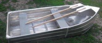
I met all these parameters. Boat weight 18 kg. And now its dimensions: in working condition, length 2.5 m, width 0.95 m, side height 0.3 m, total height 0.45 m; in transport condition: length 1.5 m, width 0.3 m, package thickness 0.08 m. The kit also includes 2 seats, a stern insert, frame stiffening tubes and oars.
Now let's talk about how we had to achieve some parameters. Buoyancy - strips of material similar to soldiers' mattresses are glued along the sides (they do not sink and are moisture resistant), the same strips are glued to the seats and feed, all the frame tubes are plastic with plugs at the ends, which does not allow water to fill them, in extreme cases, if this will not be enough (although this is unlikely) I marked places on the bow and stern of the boat for attaching 2 floats, similar to those of the rescuers from the famous TV series).
As a connecting material, I used rubber strips from the bottom, and the aft flexible part from the side of my Ufimka, mounted with glue and then riveted. I carried out all the work in my apartment, in the absence of household members - fortunately, when they arrived, the entire system was easily hidden behind the sofa.
I indicated the weight of the boat -18kg. Cost: 400 sh - plastic, 100 sh - glue and rivets, 100 sh - pipe and couplings for the stiffening frame, 50 sh - connecting screws with wing nuts and fasteners for side plastic. Everything else: rubber and oarlocks from an old boat, plywood for the seats and under the oarlocks - scraps, edging on the top of the side - scraps of pipes for drip irrigation.
And the rest is hands. I don’t know how much it might cost for sale, maybe the fishermen themselves will appreciate it? As for the pressure on the bottom seam, I distributed the main pressure (in a sitting position) over 3 seams, there is an option for a tube connection and side seams under oblique supports in the same way as the keel part. As for the flooring, a 50x60cm wooden lattice between the seats with two transverse ribs along the outline of the bottom is sufficient.
PS. The cost of materials is indicated in SHEKELS.
Production time, so slowly, is about a week.
It took a lot of time to find suitable plastic. I’m retired, so when my household left, I took everything out from behind the back of the sofa and did it. I already wrote that the rubber, rowlocks and oars I had were from a broken boat, and the rest was a matter of technique. But first I made a 25 cm model from thin plastic.
And with this boat it was easier for me also because it is my second homemade boat. The first was a frame made of plastic pipes and thin tarpaulin. When disassembled, it was no longer than a meter. In short, a bag with tubes and a cover. I want to do something like this too. That one was even lighter, and with the current choice of material, there should be shine.
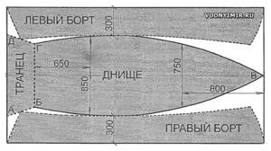
As for the pattern, everything is simple. The width of the canvas is 30cm, the short part is 1 meter long, the bow part is 1.5 meters. Step back 1 meter from the nose edge and bring it in two arcs to the middle. It is clearly visible in the photo. But I still advise you to start with a small model. There, instead of rubber, you can use adhesive tape (adhesive tape).
The model can provide all possible options, and it is much easier to correct errors. To be honest, I didn’t give any importance to the name of the plastic. At first I was looking for polypropylene, since it is not brittle and is lighter than water, but it has an exorbitant (for me) price. Then he began to select according to the principle: crushed, touched, broken.
it’s ordinary rubber, but the main condition for gluing is cleaning, stripping and degreasing the surfaces to be bonded, and mandatory soaking for min. 15 minutes after applying the glue, before joining. And I also think it is very important to additionally cover the edges of the rubber strips along the entire length of the boat with thin strips of rubberized fabric, like on factory boats.
About the changes. Already changed: the boat is designed for 2 people, but with one person the center of gravity moves to the “bow” of the boat and it goes down, and the stern rises, the wave overwhelms, so the seat for the rower was moved closer to the center of gravity, which is easy to determine from the layout -models. Regarding the height of the side, I proceeded from the maximum cutting of a standard sheet.
The boat is double in terms of the number of seats and carrying capacity. There is no need to hit anyone with oars; when there are two in the boat, then the seat is inserted closer to the “bow” of the boat, and when there is one, then 30 cm to the stern. As for convenience, it is naturally more convenient for one person, but, if desired, the boat can handle the other. Good luck!
All connections are made with rivets or screws with nuts. The sheathing is made of roofing sheet metal with a thickness of 0.2. 0.3 mm. Sheet sheathing connections are double folded and then soldered along all seams. The sheathing is fastened to the frame using petals soldered on the inside of the section. This connection ensures complete tightness of each section. The inner and outer sides of the section are covered with red lead and then painted.
The sections of the boat are connected to each other by tightening screw connectors.
The presented boat with a wooden frame also consists of three sections - bow, central and stern. If desired, the aft section can not be docked, but then the boat can only take one person.
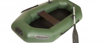
What distinguishes an avid fisherman from a simple hobbyist? Not only having a year's supply of hooks, three fishing rods and a set of worms. A real fisherman must have a boat! Yes, yes, she is! You can buy a boat in a store: a rubber one is not expensive, but it doesn’t inspire confidence; a tin, factory-made one, will be quite expensive, although it’s not clear to me what this is connected with.
The most important thing to understand before starting to build a boat is to completely discard all your subjective ideas about what a boat is, how high the sides should be. Failure of the design to comply with the basic rules of its construction, or deviation from the drawings, can lead to tragic consequences; the boat will have every chance of capsizing, taking on water, or even drowning.
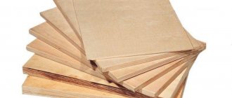
So where to start. First of all, you need to decide on the material from which the boat will be built with your own hands, whether it will be plywood or a board. In my opinion, plywood is even better, since it comes in one piece. This means you will need to think less about sealing the case.
Once the choice has been made in favor of plywood, you can begin cutting. The diagrams according to which the structure is cut can be easily found on the Internet. There is no single scheme, they are individual - do you want a big boat or a small one, with a flat bottom or not, etc. Of course, the most correct option would be to order a ready-made drawing exactly in accordance with your requirements. This approach minimizes the possibility of various types of errors in the drawings.
We invite you to familiarize yourself with: Do-it-yourself bottom tackle - types of bottom tackle, production, installation
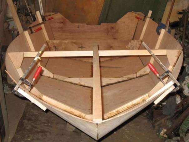
Once you have cut out the main parts, the bottom, sides, back side, you can start assembling and gluing together. Here it is necessary to take comprehensive measures to create the most durable boat hull. You will never be able to do anything alone; you need at least 2-3 people. It is best to “bend” the sides together, while a third person will fasten them with self-tapping screws or nails. After installing the elements in their places, it is necessary to securely glue the assembled body with professional waterproof glue.
When you manage to assemble the hull, you can start making frames - this is an element that gives rigidity to the boat hull and allows you to maintain the correct geometry. The frames also need to be cut according to the drawing. It is certainly impossible to say offhand what size they should be.
Don’t forget to make cuts for the stingers - guides that will run perpendicular to the frames and also affect the rigidity of the structure.
By the way, while the body of the structure is drying, you will need to install temporary slats - spacers in the upper part of the sides. This is necessary so that the correct geometry of the body is created during the drying process. If somewhere something is a little deviated from the norm, it doesn’t matter, the frames will correct it.
BOAT IN A “SUITCASE”
Even during the times of the Soviet Union, the boat “Jack Sprat” by the English yacht designer Jack Holt was popular among home-builders, thanks to its slipless assembly. But I haven’t seen any collapsible boats among them.
I have been building boats using this technology for more than 20 years. The last of them is the four-section folding boat “Jack Pot” (Fig. 1). The same but improved technological methods were used in its manufacture.
When building the boat, the main attention was paid to the simplicity and reliability of the design, appearance, speed of assembly, reducing the range of materials used, and ease of transportation and storage.
MATERIALS, TOOLS AND DEVICES
To build a boat you need: a sheet of plywood measuring 1.5 x 1.5 m, 15 mm thick and 5 sheets of 4 mm plywood of the same dimensions. You will also need a substrate on which to impregnate with drying oil, gluing, and painting parts.
For impregnation, about 15 liters of drying oil was required (you should not buy it in full at once - the consumption may be less). Below we will describe both the generally accepted technology and the technology used by the author for impregnating construction plywood with drying oil.
Rice. 1. Theoretical drawing of the “Jack Pot” boat
All wooden parts of the boat are joined using universal epoxy glue ED11. To glue the rubber gaskets (a sheet of 3 mm rubber was purchased for them) to the connecting frames, I used Moment universal glue.
ED11 adhesive is two-component (epoxy resin and hardener). It is more profitable to buy resin in large containers. Plastic containers have ring-shaped protrusions. The volume of resin between the two rings corresponds to the volume of hardener (necessary for polymerization of the glue) between the two marks printed on the label of the glass bottle in which it is sold. Since the exact dosage of resin according to the ring marks is practically impossible, I advise you to pour the resin into a glass jar, and cut off the top of the empty plastic container, leaving five marks above the bottom for the first time. Now it will be more convenient to measure the required amount of epoxy glue by pouring it in a thin stream from a jar into the resulting container.
For mixing epoxy resin with hardener. applying glue to the surfaces to be glued, removing its excess, I made a plate of 1.5 mm duralumin (can also be made of steel) measuring 150 × 15 mm with rounded ends.
Also, to apply glue when gluing strips of fiberglass and “painting” wooden parts (fenders, engine boards), you need to make a brush with a replaceable brush (for example, made of fabric), since hardened glue cannot be removed from it.
I also recommend getting a knife with a one-sided sharpening, like a “jamb” knife.
To assemble a section of a boat, you need two clamps (or better yet, five) with a solution of at least 55 mm and, possibly, several bricks.
MANUFACTURING OF FRAMES
I started making the boat with plywood frames, which I cut from a 15 mm sheet - two identical ones for each joint (Fig. 2).
I’ll share my experience with the readers: I have never seen anything better than a solid plywood frame: you don’t need any connections of frames (parts of the frame) and brackets (kerchiefs) for this.
Next, having pulled together identical frames with at least two clamps, I “calibrated” (made them identical) the pairs of connecting ones, and cleaned their edges with an emery wheel fixed in an electric drill.
Rice. 2. Rational cutting of frames on a sheet of plywood:
1 – sheet of plywood (s15); 2 - the largest connecting frame in size between the 2nd and 3rd sections (counting from the stern, 2 pcs.); 3 – connecting frame between the 1st and 2nd sections (2 pcs.); 4—connecting frame between the 3rd and 4th sections (2 pcs.); 5 – direction of wood fibers (outer, least quality layers of veneer
Then I drilled holes in them for the M6 mounting bolts: first I marked them with an awl, then I drilled them with a 3 mm drill, and then a 6 mm drill along them. The holes are spaced from each other at a distance of approximately 150 mm, and from the outer edge of the frame - by 20 mm (it was possible to retreat 25 mm).
Subsequently, the frame is removed from the frames, to which the skin is glued at an acute angle, and a bevel is made with a rasp along the bend of the bottom. The angle of the fry was measured on a section assembled on twisted wire. Actually, you can make a calculation with sufficient accuracy and cut at an angle with a jigsaw, but I haven’t worked with this technology yet.
Finished hull of the sectional boat “Jack Pot”
The dimensions of the connecting frames can be calculated based on the length of the sections by drawing frame lines in all three views shown in the theoretical drawing. The distances along the two edges of the pattern from the theoretical to the connecting frame can be calculated as the length of a straight line using trigonometric functions or the Pythagorean theorem. But it’s better to first make a collapsible model from cardboard at a scale of 1:3 or 1:5.
SQUARE
After making the frames, I started cutting out sheets of section cladding from 4mm plywood. To build a sectional boat, you need fairly accurate shell blanks (the errors in length should not exceed 1 mm per section, and in width and for connecting frames - even less). Therefore, first I made patterns from sheets of whatman paper and used them to adjust the dimensions of the frames and skin (mostly the errors turned out to be less than a millimeter).
It is better to cut plywood sheathing not with a jigsaw, but with a hand saw with fine teeth.
The direction of the fibers of the outer layers of the bottom skin coincides with the center plane of the boat. The internal linings on the bottom have a transverse fiber direction. The skin belt adjacent to the bottom (between the cheekbones) was made “transverse”. The direction of the fibers of the side sheathing also coincides with the center plane. The load from them, in addition to the frames, is also taken up by the fender.
For both transoms, the direction of the skin fibers is horizontal. I did not remove the malka from the casing, for which I “paid a certain price” in terms of labor intensity of production, but it is not so significant (more on this below). But the strength of the skin joints on the cheekbones may even have increased.
IMPREGNATION
The traditional technology for impregnating a boat with drying oil is simple. Drying oil is poured into a tin can with a volume of 0.8 - 1 liter, 3 - 4 cm below the edges, brought to a boil, poured inside the section and smeared along the sides with a large paint brush. Sometimes the section is also warmed up. After the drying oil stops being absorbed from the inner surface of the skin, the section is turned upside down with the keel. Using the same paint brush, apply boiling drying oil from a can to the outer surface of the sheathing. The brush should be stored in a jar with acetone between impregnation works with drying oil. After this, the hull casing is not painted either outside or inside.
If you are a gambling person, then https://wulkansloty.com/lucky-haunter/ is for you.
The proposed technology for impregnating plywood with drying oil differs from the traditional one. For this, there is a device (Fig. 3), which is a steel (made of 1.2 mm sheet) vessel with dimensions 900x520x30 mm. The vessel on a special frame is installed on a gas stove at an angle of 45°, and plywood sheets or frames are placed in it. It should be noted that epoxy resin must first be applied to the edges of the sheets and the surfaces of the frames where the fiberglass tapes will be glued, and by the time of impregnation it has polymerized. Next, drying oil is poured into the vessel and heated to a boil. Usually I bring the drying oil with a package of plywood parts to a boil twice and remove it from the stove after it has cooled.
Rice. 3. Apparatus for complete impregnation of plywood sheathing sheets and frames with boiling drying oil:
1 – vessel 900x520x30 (steel sheet s1.2); 2 – bed; 3 – household gas stove
As a result, the plywood is completely saturated with drying oil and acquires a brown color. The entire lining and frames of “Jack Pot” absorbed exactly 15 liters of drying oil. Full impregnation provides excellent water resistance and increases the strength of the skin.
GLUING TECHNOLOGY
First, the sheathing sheets were assembled on twisted wires (twisted to the outside of the body, as shown in Fig. 4). In this case, there is no need to tightly twist the twists of the wire - to allow for a slight but free displacement of adjacent sheets of sheathing relative to each other and for the convenience of getting the wire into the hole (steel tie wire - 1.5 mm in diameter, copper - 1.8 mm). I perform this operation on the table. When all the twists are done, you can tighten them with pliers.
Rice. 4. Cross-section of the zygomatic joint of the section sheathing sheets (along the wire twist):
1.2- considerable forged sheets of boat sheathing (s4 plywood impregnated with drying oil); 3 twisted wire (annealed steel wire Ø1.5, cut to the bracket flush with the sheathing); 4 – 1st layer of epoxy glue; 5 – first fiberglass tape; 6 -2nd layer of epoxy glue: 7 – second fiberglass tape glued on top of the first (the number of glued tapes is up to 4); 8 – epoxy putty (resin with sawdust)
I started assembling the sections from the bottom. The frame was applied with its lower edge to the bottom plating sheet (the difference was removed on the frame). Then a similar operation was carried out with the zygomatic and side skins.
The Jack Pot boat was designed in such a way that it could be carried when folded, like a suitcase. - by the hand. This imposed restrictions on the vertical dimensions of the package (according to my height - about 570 mm). This condition determined the size of the boat; length – 2100 mm. width – 1157 mm.
Where the skin and the edges of the frames meet at an obtuse angle, the gap between them after assembling the section is sealed with putty (Fig. 9). An obtuse angle with the skin in the second section is formed by two frames, in the third - one.
After gluing the section skin joints, I sealed the triangular grooves on the cheekbones from the inside at the junction of two large forged sheets of skin. The grooves were also sealed with epoxy putty with wood powder and, after polymerization of the glue, I cleaned off the excess with an emery wheel using an electric drill (the wood powder was collected after cleaning the fenders with the same attachment).
The next operation is gluing in the connecting frame. The section is in the “overkill” position (bottom up, Fig. 5) on a table of sufficient area. Clamps are used to press the frame against the skin of the section bottom.
Rice. 5. Assembly of the section (connection of the frame with the casing; a, b, c, d – sequence of operations):
1 – boat section sheathing sheets; 2 – docking frame: 3 – twisted wire; 4 – clamps; 5 – large “flies” 40×30 mm for a guide nail and two fastening nails: 6 – guide nails; 7 – fastening nails; 8 – plastic container with epoxy resin and fixative; 9 – spatula for mixing epoxy glue; 10 – sections of the frame and sheathing with epoxy glue applied: 11 – bent fastening nails; 12 – fastening “two-nail” “flies”
To perform this operation, 80-100 rectangles (“flies”) measuring 30x10 mm are cut from scraps of 4 mm plywood. For all “flies”, the direction of the fibers of the outer layers of veneer should coincide with the large sides. We drive the 25 mm fastening nails through the “fly” not completely, but leaving about 5 mm. and bend this end so that the cap is on the edge of the “fly” - the nail will be easier to remove in the future (Fig. 5). First, I hammer two nails into the “fly” not far from the edges, then I bend them one by one, trying to ensure that the head hits the corner of the “fly” and hangs slightly over the edge. I hammer in the fastening nails at a distance of 4-5 mm from the edge of the section skin, coinciding with the joining surface of the frame. The name “two-nail fly” does not mean at all that you cannot hammer another nail or two into it if necessary.
Four “flies” should be made in large sizes - 30x30 mm - for a 60 mm guide nail and two fastening nails. These “flies” should be positioned in the same way as small ones, with the fibers directed across the boat. Gluing frames into the second and third sections (from the aft transom) is more difficult due to the fact that in these sections two frames are glued: the skin placed on the frame turned upside down tends to fold, the frame tends to fall out. Therefore, for training, I first glued the frames into the stern and bow sections. The area where the frame and skin are glued must be degreased with a solvent. All “flies”, not excluding the guides, are installed with their edges along the cut line of the skin and frame, for better control of their coincidence (Fig. 5) and the line of driving fastening nails. Under the guide nails, holes are drilled in the “fly”, sheathing and frame during fitting (Fig. 4) without glue so that it hits the middle of the edge of the frame. I place the guide “fly” on the edge of the bottom skin, close to the cheekbone, so that in the future it will serve as the most powerful fastening “fly” (Fig. 5).
The sequence of work is as follows. The frame at the place of future gluing is pressed (without glue) to the bottom skin with two clamps (Fig. 4a). Two or three guide “flies” are nailed with fastening nails to the edges of the bottom skin (to the line of the first cheekbone). The nails are driven shallowly, just to catch the fly. Then a hole about 20 mm deep is drilled through the “fly” for the guide nail. The latter achieves another 8 - 10 mm, that is, more than 30 mm of the guide nail remains outside (above the “fly”). After this, the clamps are removed. The frame is lowered - the head of the guide nail rests on the outer plane of the guide “fly”. A gap is formed between the frame and the inner surface of the bottom skin, sufficient for applying epoxy glue to the edge of the frame and the edge of the skin.
If you glue frames without fenders, then glue is applied to the skin and frame to the level of the second cheekbone or slightly higher. Then the frame is again pressed against the skin with clamps (this is not reflected in the pictures). In the guide “flies”, the fastening nails are driven in so that about 5 mm of nail remains above the “fly”, which are bent. First, I nail the “flies” every 40 – 80 mm, and then I put one or two more between them.
Similarly, other sheets of sheathing after the first cheekbone are nailed with fastening “flies”. There are no guide nails or guide “flies” on them, so you have to control the coincidence of the cut of the sheathing sheets and the plane of the frame with your hands, then pressing the sheathing sheet to the frame with a clamp, or by shallowly driving in a fastening nail without a “fly”. If the frame is glued without fenders, then the side sheets above the second cheekbone are nailed with one or two “flies”. Above, the side skin is not glued to the frame until the fenders are installed. This is due to the fact that in almost all sections the fender beam has a significant curvature and, being attached to the side skin, will either bend the upper ends of the frames or tear off the gluing.
Thus, if you glue the frame completely at once, it is necessary to set the curvature of the uppermost part of the side skin. To do this, you need to make fender bars in advance with a reserve length for locks (plus another 10-30 mm) and attach them with screws from the outside to the upper edge of the side sheet. However, after gluing in the frame, the fender will most likely need to be rearranged and leveled across adjacent sections. In addition, the fender will not allow the most important upper “flies” to be clogged. Therefore, for gluing the frames, I made technological internal fenders-conductors for the curvature of the side. (Both jigs can be made at once when making structural fenders: you just need to take a board of sufficient width, then the part to be cut will be the jig). The conductors are attached to the inner upper part of the side skin with three screws. The conductor should be several millimeters smaller than the distance between the section frames. The need to set the curvature of the upper part of the side plating with jigs, in case of jigless assembly, is a fee for a dismountable structure (on a non-dismountable boat, the side plating itself acquires the required curvature. After gluing the frames and plating, it is necessary to fill the gaps between them. For this, the coarsest and thickest putty is suitable.
Next, I glued the longitudinal joints of the skin on the cheekbones inside the section with a narrow fiberglass tape (30 mm wide). Before this, the areas where the epoxy glue was applied were degreased with acetone. The ends of the tapes were bent and glued to the frame to the full height - 50 mm (Fig. 6). The glue was applied only to the edges of the sheathing sheets (15 mm each) and in a 30 mm strip to the frame.
Rice. 6: Gluing joints with epoxy glue and fiberglass tapes:
1 - plastic container with epoxy glue (resin and fixative); 2 – disposable brush for applying epoxy glue; 3 – docking frame: 4 – plywood sheets covering the boat section; 5 – previously glued fiberglass tapes, which formed fiberglass after polymerization of the epoxy resin; 6 – a layer of epoxy glue applied with a brush to the internal surfaces of the skin and frame at the places where the fiberglass tape is applied; 7 – fiberglass tapes gluing rectangular joints of the skin and frame; 8 – spatula for stirring epoxy resin and fixative
The joints of the transoms with the longitudinal sheathing sheets are also covered with narrow fiberglass tape.
After gluing the joints and polymerizing the resin, I cut off the wire twists from the outside with pliers.
Then I glued the joints of the frames and transoms with the sheathing sheets. Before this, I used a wire brush to clean and degrease the areas where the fiberglass tapes were glued. Here, epoxy glue is applied more generously than on the cheekbones of the skin, and the joints are covered with pieces of fiberglass tape with an overlap of up to 100 mm.
It is impossible to cover a joint without defects with one long tape. In addition, pasting overlapping pieces of fiberglass tape strengthens the places that require such reinforcement - longitudinal and transverse joints of parts. The sections on which the tapes were applied remain on the desktop. Within half an hour, the quality of the sticker is monitored and corrected if necessary.
Before gluing the next layer of fiberglass tapes, I clean the previous one with a wire brush and an electric drill. At the same time, I remove individual fiberglass threads, cut off the folds, and open the fiberglass bubbles formed in the places of twists (but not completely, but leaving “cups” so that during subsequent application the epoxy glue will linger in them). In this case, scratches are applied, which contribute to more durable adhesion of the next layers of fiberglass tapes. If an air bubble forms above the twist and after gluing the second layer, the operation must be repeated in this place. After cleaning, degreasing is carried out with acetone.
The number of glued fiberglass tapes is four, the approximate width of the tapes is 30, 45, 55, 62 mm. Already the first glued tape should be “guaranteed” to overlap the 10 mm wire twists in width.
I cut and prepare fiberglass tapes for gluing with ordinary scissors so that the longitudinal threads of the fiberglass are not cut. The option that immediately arises is to pull out the longitudinal (in the direction of the cut) thread from the fiberglass fabric (which determines the width of the tape) and use the resulting gap as a marking line when cutting the tape with scissors.
I used this method on fiberglass fabric of a very rare weave (the distance between the threads reached the diameter of the thread itself). In addition, the ends of the threads were not secured. The threads were pulled out from the edge of the canvas with tweezers. If the thread did not protrude beyond the edge of the canvas, I pry it with an awl or needle 10-15 mm from the edge, pull it out a few centimeters with tweezers and pull it out completely with my fingers.
On dense fiberglass, the threads are pressed against each other and secured to the edges of the roll, and it is very difficult or impossible to pull them out. A different technique was used here. Using a soft pencil, marks were made on the canvas at a distance from the edge of the canvas, which determined the width of the tape, at intervals of 100 - 150 mm. First, the cut threads were removed from the edge of the canvas, which was obtained as a result of cutting the previous tape, in order to determine the “real” edge. Then, using a short (150 - 200 mm) ruler, these marks were connected to each other. The result was a broken cutting line. I cut four or five strips, after which the operation of determining the “real” edge of the fiberglass and pulling the threads from the edge of the fabric was repeated to correct the direction of the cut.
It should be noted that when working with rare weave fiberglass, time is saved on marking and cutting tapes. But. that's the main thing. that all places of this tape, when gluing, adhere much more tightly to the surfaces being glued. As a result, there are practically no defects. The disadvantage in this case is the need to glue more strips of fiberglass to ensure the necessary strength.
I consider it possible to use any type of fiberglass, especially when the boat is made in a single copy. One piece of advice. If you have both fiberglass fabrics, then it is advisable to cut narrow strips from the dense ones (the narrower, the fewer defects), and use the rare ones for pasting first.
Fiberglass fabric is produced either with or without paraffin impregnation. Easy to distinguish. Impregnated fiberglass is yellow in color and greasy to the touch.
Before gluing with epoxy glue, paraffin should be removed from impregnated fiberglass fabric: either soak it in a solvent or calcinate it. The criterion for the end of annealing is the absence of smoke that has ceased to come out of the fiberglass rolls of tape. I calcinate all fiberglass.
FEATURES
The blanks for external fenders have a cross-section of 30×20 mm (Fig. 7, 10). Later, it became clear that the thickness of the timber should be at least 25 mm, so as not to reinforce the locks, for example, with metal plates on top and bottom, which is even simpler and stronger.
The bevel was made with a rasp on the underside of the fender beam (which is attached to the side sheathing), measuring the angle between the end of the frame and the side sheathing with a protractor (Fig. 6a).
The fenders are initially attached to the side sheathing with at least five screws (from inside the section). When gluing parts, the number of screws doubles. Before this, the fender beams are aligned along the upper edges of the frames - this preliminary fastening is necessary to impart curvature to the side plating. In this case, the side trim can be either slightly higher or lower than the fender. If it is higher, then it is ground off with a grinder; if lower, then this can be corrected with epoxy putty.
The locks of the fenders of adjacent sections of the hull are joined “half a tree” (Fig. 7). The protruding spike is always at the bottom. The order of alternating tenons of the fender locks extending beyond the longitudinal dimensions of the section can be seen in Figure 10. The largest section (second from the stern), into which all other sections are inserted during assembly, does not have protruding tenons of the fender locks (so as not to protrude from the “ suitcase”, but more on that later).
Rice. 7. Locks of the fenders of the docking frames:
1 – fender; 2 – side trim; 3 – docking frame
*rep. Ø6 drill simultaneously with the adjacent fenders with a closed chic after assembling the boat sections with relin gaskets
Gluing the fenders to the side skin is done on the assembled adjacent sections of the boat. After applying epoxy glue to the previously degreased surfaces of the corresponding sides of the fenders and the gluing strip on the side skin, the locks of adjacent sections are tightened with clamps, after which the fender is screwed in place. Then the coupling bolts of the frames are unscrewed and the sections are separated to prevent the locks from sticking together (this can be avoided by isolating the locks from each other with plastic film, but I thought of that later).
The stern fender is twice as thick as the side fenders (40×30 mm) - two strips with a cross-section of 30×20 mm are glued together (Fig. 7). To use a low-power outboard motor, a board with a cross-section of 135×16mm is glued vertically to the aft transom from the top of the fender to the bottom trim. A groove of the same dimensions is made in the bottom plank, the board is inserted into it and glued to both planks. For pressure when gluing the board, several bricks and thick books wrapped in plastic bags were again used.
The fenders of the stern and bow transoms are connected to the side fenders, also with half-tree tenons, but without a wedge (Fig. 8. 9). After attaching them with screws to the side skin, holes with a diameter of 6 mm were drilled in the center of the tenons for tie-down during gluing M6 bolts with large diameter washers. At the stern, the studded connection of the side fenders is made only with the upper strip of the aft fender (Fig. 8). The fenders of the bow and stern transoms are straight (of course, they can also be made convex).
Rice. 8. Boat stern transom (1st section):
1 – stern transom sheathing (s4 plywood with horizontal fibers of outer layers); 2 – under-engine board (section 135×16 for a low-power outboard motor): 3 – upper bar of the stern fender (section 30×20, with locks): 4 – lower bar of the stern fender (section 30×20, with locks) groove for the engine board); 5 – side fenders (section 30×20); 6 – section covering (s4 plywood); 7 – 1st connecting frame (s15 plywood); 8 – gasket (rubber s3)
*rep. Ø6 for technological bolts (sealed with putty after assembling (gluing) the section
Rice. 9. Bow transom of the boat (4th section):
1 – bow transom sheathing (s4 plywood with horizontal fibers of outer layers); 2 – bow (final beam (section 30×20 with locks); 3 – side fender beams (section 30×20); 4 – section covering (s4 plywood); 5 – 3rd connecting frame (s15 plywood) ; 6 – gasket (rubber s3)
*rep. Ø6 for technological bolts (set with putty after assembling (gluing) the section
After gluing all the fenders to the skin, I sanded them with sandpaper using an electric drill.
The resulting wood powder was collected, sifted and subsequently used to prepare putty. Then the fenders were covered with epoxy resin.
RUBBER INTER-FRAME PADS
To make rubber gaskets between the connecting frames, I had to buy a sheet of 3-mm rubber with a corrugated surface (there was no spongy rubber, like old inner tubes from car wheels). Irregularities less than 0.5 mm are located randomly. The most rational cutting of rubber gaskets is the same as for connecting frames, only there are not six gaskets, but three. The markings were made with correction fluid (to correct errors in the text). The section with the required frame is placed “on its butt” on a spread sheet of rubber with the required frame down (Fig. 10) (the protruding parts of the fender locks can be hung over the edge of the table). I put two or three bricks on top of the frame. Using a corrector brush, I apply the contour line of the frame with the skin glued to the outside onto the rubber. The line is even more than 5 mm wide in some places - no problem. Using scissors, cut out the gasket with a margin of about 5 mm.
Rice. 10. Cutting out rubber gaskets with allowances (a) and holes in them and bolts for frame joints (b):
1 – sheathing of a boat section; 2 – docking frame; 3 rubber gasket: 4 – side fender; 5 – “squeezer” (steel tube Ø6x1 with a sharp chamfer at the end and a wooden handle); 6 – M6 coupling bolts (10 pcs. per joint); 7 – bottle with correction fluid
Next, I made a tool for making holes in the rubber gaskets. I’ll call him “salesman.” Of course, you can drill holes in the rubber gasket with a drill, but it will not be so neat.
The internal diameter of the working body of the “punch” – tubes with outer edges sharpened with emery – is 5 mm.
We place a sheet of plywood on the table, a cut rubber gasket on the sheet, and a section of the body on the gasket. In this case, the latter may have fenders with lock spikes extending beyond the joining plane of the frame - then place the section on the edge of the table so that the spikes hang down. Using a “punch”, pressing and turning it, we cut holes Ø5 mm. We take out the tool and use a bicycle spoke to push the rubber roller out of the tube. Immediately insert a coupling bolt into the resulting hole in the gasket to secure it. After pushing through all the holes, the section is turned upside down. The gasket is cleaned with sandpaper fixed on a wooden block, degreased with acetone, and coated with “Especially Strong Moment” glue (but contrary to the instructions, the glue was applied only to one of the surfaces to be glued - to the gasket and did not sit for 15 minutes). Immediately I placed the adjacent section on the gasket and tightened it with coupling bolts and wing nuts. After 24 hours, I cut off the excess gasket extending beyond the skin and frame flush from the outside and inside of the boat with a sharp knife. After that I removed the bolts.
Rice. 11. Hull of the sectional collapsible boat “Jack Pot” (top view):
1 – aft fender; 2 – side fender: 3 – side plating; 4 – zygomatic lining; 5 – bottom trim; 6 – additional bottom plate (plywood s4); 7 – docking frames; 8 – interframe rubber gasket: 9 – bow transom trim; 10 – bow fender
The boat hull is assembled; on the aft transom, a reinforced (twice as thick) mooring beam and a vertical under-engine board, not shown in the drawing, stand out
Rice. 12. Layout diagram of sections for transportation and storage:
1 – sections of the boat; 2 – rubber sealing gaskets, glued to the frames with “Extra-Strong “Moment”” adhesive: 3 – sectional parts of the side fender
* lines with arrows indicate the order of laying sections one into another; half-lance lines with arrows indicate that this section, before being inserted into another section, rotates 180°
After the sections are manufactured, they are assembled with bolts into a single body (Fig. 11) or folded into one another for transportation or storage. The diagram for folding the boat (which sections go into which ones) is shown in Fig. 12. The weight of the boat is about 33 kg.
(To be continued)
L. RZHEVSKY, Obninsk, Kaluga region.
We recommend reading
- ON ASPHALT - WITH A BOAT MOTOR Having read the headline, you might think: the motor is being repaired. Nothing like this. This five-horsepower "Surf" is in excellent condition. But it is not installed on the boat, but on the original one...
- “UNIVERSAL” FOR CHARGING BATTERIES Small-sized disk batteries are widely used in electronic equipment and in amateur radio design. But charging them is not easy. Purely constructive ones also get in the way...
How are homemade plywood boats made?
It is quite possible to create a small, stable, capable of lifting 2-3 people on board and at the same time a light vessel, capable of sailing both with the help of oars, a motor or a sail, without special training, since boats of this class can be created even by beginners . And it is precisely for such homemade products, which use the simplest tools and have limited funds, that the most affordable material is plywood.
Durable and at the same time easy to process with both electric and hand tools, plywood is very widely used not only in the construction of small vessels, but also quite respectable sea yachts.
Oddly enough, for self-building a boat, the most necessary condition is a properly selected room in which you can freely place the boat, while a prerequisite is the presence of ventilation and, when working in the cold season, heating that can maintain a comfortable temperature for work and prevent temperature changes air.
When making drawings you will need:
- drawing supplies:
- pencils;
- elastic bands;
- patterns;
- long metal rulers and large triangles;
- line;
- cardboard and drawing paper;
- paper glue;
- calculator;
During the construction process you will need:
- electric jigsaw;
- hammer;
- axe;
- clamps (and most likely a lot - at least 10 pieces);
- brushes, metal spatula, rubber spatulas;
- screwdriver;
- hand planes or electric planes;
- screwdrivers;
- chisels;
- stapler;
- hand saws and electric circular saw;
The following materials are recommended for manufacturing:
- plywood of standard sizes 1.5m * 1.5m;
- boards – pine, oak:
- fabric for covering the body;
- putty for sealing cracks and joints of sheets;
- special waterproof glue;
- natural drying oil or water-repellent impregnation for wood;
- oil paint (if the owner is an adherent of the traditional method of painting the hull) or special enamel for ship hulls;
- nails, screws, self-tapping screws;
- metal strip, metal for oarlocks and fastenings;
The optimal parameters for a boat made of plywood with a thickness of 4-5 mm are:
- the total length of the hull from bow to transom is 4.5 meters;
- width at the top at the widest point of the body – 1.05 meters;
- The depth of the boat is 0.4 meters.
The main element of the boat frame is the keel - the base on which all other parts of the hull are attached.
The bow of the boat, formed by the stem, is attached on one side, and in the stern there is a sternpost. These are the elements responsible for the longitudinal rigidity of the structure. They can be either solid wood or composite - glued together in separate parts, and secured with nails or screws.
Hull bends and transverse shapes are formed thanks to frames - transverse elements of the hull, giving it additional rigidity. The boards on top of the stem and the sternpost, connected to the frames on both sides, form the sides.
The frame thus obtained is sheathed on top with plywood.
A flooring is made inside the boat - a slant, which acts as a lower deck so as not to stand on the bottom of the boat.
Boats for using a motor are not fundamentally different from those designed for oars or sails. The main difference here is that the stern is modified to mount the engine - they have a transom board or transom made of multi-layer plywood that can withstand the engine mount.
Some more modern boats may also have other elements of small vessels of this class - a cockpit, deck stringers, side stringers. To ensure buoyancy, such boats are provided with sealed niches filled with foam that can keep the boat on the surface in the event of capsizing.
Drawings of a homemade collapsible boat
Drawing up a drawing is actually the most important stage in building a ship. In some cases, it is recommended to use drawings posted on websites and in the public domain. But even here it is necessary to show maximum care and imagine all the stages of the work and the components of the vessel.
It is recommended to draw a scale drawing on graph paper; such construction will allow you to calculate all the details of the body.
The stage of constructing a general sketch of a drawing can be represented by the following algorithm:
- an axial or diametrical plane is drawn, this is a line dividing the body lengthwise into two equal parts. Since the boat has a symmetrical image, the drawing requires a perfect fit of all elements.
- the center plane (DP) is divided into equal segments, these will be the locations of the frames;
- a vertical projection of the boat and a top view are drawn;
- plans of frames are drawn along transverse lines;
- The consistency of the location and scale of all elements is checked.
- The completed sketch of the frames is drawn on a scale of 1:1; it is recommended to draw the drawing on this scale on hard paper or cardboard, this is done to facilitate transfer to plywood or wood.
- It is recommended to make the smoothness of the bends at the marked points using a metal ruler, from the side to the keel.
After checking the symmetry of all parts, they are transferred to cardboard. Such a cardboard template is necessary to facilitate the manufacture of wooden elements. Templates are transferred to wood with precise adherence to the contours, without adding additional allowances or increasing dimensions.
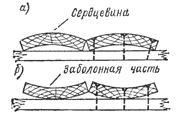
When transferring templates to boards, you need to follow the order of the fibers so that they run across as little as possible.
The central and aft sections are identical in design and differ only in size. They consist of two bulkheads and longitudinal strips of 15-thick multi-layer plywood. 18 mm. The sides, bottom and outer sides of the bulkheads, as in the first case, are covered with metal (tin) sheathing.
First, cut out the bulkheads from the plywood. To make the structure easier, use a jigsaw to cut out the inside of the bulkhead. Then prepare longitudinal plates - strips of the same material. Treat the cut ends of the plywood with a large file, then with abrasive sandpaper and be sure to soak them in several layers of drying oil.
Make the bars for the frame of the bow compartment and bulkheads from well-dried pine without branches. Adjust the joints of the bars as accurately as possible. Attach the bars to the bulkheads with screws, having previously glued them with casein glue. After attaching and drying the glue, cover the bars with two or three layers of drying oil.
The drawings show the main dimensions of plywood and timber parts; during assembly and adjustment, in some places you will have to deviate from the indicated dimensions within 2...5 mm. The main thing is that the main overall dimensions are maintained and that there is no curvature of the frames after assembling the sections, so that the coaxiality of the sections and symmetry from the center line of the boat are maintained.
After making the frames, you can start sheathing. Each plane of the frame must be covered with a single sheet of tinplate. It is best to apply the sheet to the plane and outline it around the perimeter, then you need to make an allowance on each side. Make the width of the allowance different (see figure). At the junction of the side and the bulkhead with the bottom, leave an allowance of 10 mm on the side and bulkhead sheet, and at the bottom sheet, the allowance will be 15 mm. At the junction of the side and the bulkhead, leave 10 mm on the side, and 15 mm on the bulkhead.
We suggest you read: Which float rod to choose?
Adjust and bend the sheet cladding directly on the frame. First, use pliers to bend the tin edges at the corners by approximately 90°. Having done this, make sure that the edges of the joined sheets are parallel. When the parallelism of the edges is established on all sides, you can bend the seam along the entire length completely.
Tap the first bend on the crossbar. Then make a second bend and after that, release the sheathing from the frame and secure the seam by tapping it with a mallet along the entire length, placing the crossbar on the back side. You should end up with a rectangular tin container, into which insert the appropriate frame from the section.
Check that the sheathing planes fit tightly to the frame parts in all places. To do this, it is better to place the section on a flat floor and step on the longitudinal bars of the bottom with your feet. Pressing the frame against the sheathing in this way, secure the sheathing at the top of the sides in several places. Then you can thoroughly attach the skin to the frame and completely trim the top edge of the side skin, bending the skin along the entire upper perimeter of the section with a double fold.
Solder the seams with a large soldering iron. It is strictly forbidden to use a blowtorch - there is a high probability of setting the frame on fire. If you know in advance that you cannot cope with soldering, then before making the seams (before the first bend), you need to treat the inner edges of the sheets with automotive sealant.
Lastly, secure the section connectors according to the drawings. The dimensions of the connectors are shown in the figure.
All that remains is to treat all sections of the boat with red lead (preferably “marine”) and, after drying, paint them in your favorite color.
It is better to make oars for the boat from aluminum tubes. It would be nice to adjust the tubes in such a way that they can be inserted into one another, then you can make retractable oars that, when assembled, take up little space.
The pictures show one of the options for constructing telescopic oars and their oarlocks.
To ensure that the boat is completely unsinkable in the event of a capsize, it is a good idea to make foam floats and secure them to the inside of the bow and stern compartments.
Today, the most popular boats are the “Stitch and glue” design, which translates as “Sew and Glue”, most of these drawings are sold in full scale, this makes the construction process simpler.
One of these structures is “North 520”.
North 520
These are drawings for a motor boat. It can accommodate up to 7 people at the same time, and there are also 2 sleeping places. Its length is 5.2 m and its width is 2.08. It is recommended to set the engine from 50 to 100 horsepower.
This model is very convenient and practical, but the cost of its construction will exceed 100 thousand rubles. A more affordable design is the Breeze-42.
Breeze-42
At first there was the Breeze-26 model, it was designed for only two people, but it worked well in tests, so it was decided to make a larger version. This is how “Breeze-42” appeared.
From his predecessor he received the appearance and narrow bottom. The drawings include luggage compartments, a deck and a step. It can accommodate four people at the same time. Oars are used, but an engine with a power of no more than 8 hp can be installed.
Stronger options will lead to trim, so the speed will not increase. It is not afraid of bad weather either; it is possible to pull out an awning.
To build it with your own hands, you use wood and plywood sheets. With a fairly long body (4.2 m), the weight will be only about 60 kg. Waterproof materials provide the necessary safety of the structure.
Among the compact options, you should pay attention to the tuzik-kartop. This model can be considered a more modern modification of the “Goldfish”. They have almost the same length, but the tuzik is a little wider and has high sides.
The flat bottom and high side provide the necessary safety of the structure. This boat can accommodate two adults and one child. It is perfect for relaxing on the pond or fishing. It is possible to use a sail. Moreover, the weight is only 35-40 kg, which allows you to easily transport it on the roof of a car.
The bow of the boat may seem a little strange, but it is very functional. Thanks to this bow, the carrying capacity increases and provides high stability on the water. In addition, such forms greatly simplify the assembly process.
"Duck-2"
This design is very popular among fishermen and hunters. It is equipped with low-power motors, and it also has a shallow draft, which allows it to sail in shallow water and in thickets.
“Duck-2” is also good for walking along ponds; it is possible to install a sail.
It easily accommodates two adults with a lot of gear. If along the way you run out of fuel or the engine stalls, the movement continues thanks to the oars.
The speed of the vehicle with the engine turned on will be up to 25 km/h, with oars approximately 5-6 km/h. The small fin allows you to move straight when paddling.
This option is perfect for novice shipbuilders. It’s not difficult to make it yourself, and the engines and plywood are inexpensive.
If you can’t find the drawing you need, you can make it yourself. See drawings and our recommendations for building a boat trailer here.
The keelson is the most loaded unit and must have a sufficient margin of strength and rigidity. It is preferable to make it from ash slats measuring 40X 15X 1100 millimeters. The keelson consists of three parts - stern, middle and bow (Fig. 2).It is advisable to start assembling it from the middle part. To do this, I select straight slats of the same height and width, which I install on temporary spacers 120 mm long and 40 mm high and secure with screws. At the ends of the slats in a vertical plane, I drill holes with a diameter of 4 millimeters for M4 screws for subsequent fastening of the support strips made of 10 mm plywood. After installing and securing the strips with epoxy glue and screws on both sides, as well as stops according to the dimensions of the frames and limit strips, I remove the temporary spacers. Boat frame drawing
Next, the bow and stern parts of the keelson must be carefully adjusted to the middle part and the measuring spacers must be installed. The inner sides of the slats at one end must be reduced to a cone (5X 50 millimeters) with a plane, then assembled with the plates of the bow and stern parts of the keelson and secured with rivets with a diameter of 3 millimeters. The mating surfaces of the bow and stern parts must fit tightly, without gaps, into the internal cavity of the middle part of the keelson. Having completed the general assembly of the keelson parts with each other, as well as with the stem and sternpost, I drill holes with a diameter of 4 millimeters in a vertical plane at the ends of the slats - for fastening the thrust (fixing) strips with M4 screws and nuts.
For greater strength and rigidity of the connections of the keelson parts with the support and thrust strips, before installing them, I apply an adhesive composition of epoxy compound - 100 parts and polyethylene polyamine - 12 parts by weight to the cleaned contacting surfaces. I keep the parts to be glued under load for 24 hours.
Sternpost and stem (Fig. 1)
I install it during the general assembly process. I secure the lower end with rivets with a diameter of 3 millimeters; I drill the upper hole with a diameter of 4.2 millimeters after installing the sternpost and stem at angles of 10 and 20 degrees according to the template. Fastening is done with M4 screws and nuts.
Frames (Fig. 3)
made of slats with a cross section of 17X20 millimeters.
The side branches and bases are connected to each other with rivets and gussets. I select the length of the base and the bevel angle p according to the table (see Fig. 3)
.
The angle of inclination of the side branches of the bow frame is 15°, the rest - 10°. I install the side branches hingedly and fix them according to a template cut out of cardboard. Through the holes in the gussets, I drill holes in the side branches for rivets with a diameter of 3 millimeters and M4 screws, in accordance with the dimensions indicated in Fig. 3.
During the final assembly of the frame, on the upper part of the base of frames 4 and 11
(Fig. 1),
I install upper and lower locks for attaching the deck and frame to the keelson. On the side branches from the outside I install loops for attaching the upper stringers to the frames, and on the lower part - a fastener for connecting the lower stringers to the frames.
Transom (Fig. 4)
made of slats with a cross section of 15X 20 millimeters.
It consists of two side branches connected to each other by the base and the upper rail using gussets, rivets and M4 screws. The joints are hinged, which allows the parts to be folded into a case. On the sternpost, the transom is secured with corners and a lower lock.
Stringers (Fig. 5)
I make it from flexible slats with a cross section of 20 X 12 and a length of 1100 millimeters, connected to each other using hinge locks.
I install eyelets and hooks on the bow and stern sides of the finally assembled stringers. In this case, I hang the bow eye and connecting hooks after the final installation of the frames on the keelson, securing the stem and sternpost: First, I mount the lower stringers, after which I install the upper stringers along the actual length.
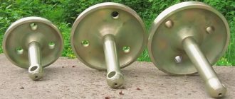
Oarlock assembly (Fig. 6)
I attach the oarlocks to the rail
(Fig. 1),
which I install in place during the general assembly of the frame using screws and M5 wing nuts.
Assembled oar (Fig. 7)
consists of a handle, a lock and a blade. The oar lock has a bevel and two rings with a diameter of 40 millimeters, fixed motionless with screws and epoxy glue. I carefully adjust the bevel and rings so that there are no gaps or play between them, impregnate them with waterproof varnish, dry them, finally connect them and drill a hole with a diameter of 4.5 millimeters for an M4 screw and a wing nut.
I make the oar blade from plywood or aluminum sheet 1.0-1.5 millimeters thick. I bend the plywood according to a template, dry it, sand it and coat it with waterproof varnish. It is much easier to make a blade from an aluminum sheet: just cut it along the contour, clean the sharp edges, bend it according to a template and make stiffening ribs along the edges. I attach the blade to the rod using rivets with a diameter of 3 millimeters.
I perform the general assembly of the frame in the following sequence. I assemble the keelson, install the frames, transom, lower stringers, upper stringers and secure them in accordance with the fastening points shown in the drawings. In the lower stringers, the eyes must be bent at an angle of 90° so that they can be secured to the transom with M4 screws. In the bow, I install the eyes in place after securing the stern struts and the stem struts. Having secured the upper stringers to the transom and stem, I install the hooks (see position 3 in Fig. 5)
using screws 2.5X 10 millimeters.
If the wood is very dense, then you have to drill holes with a diameter of 2 millimeters for the screws. When the frame is finally assembled, I file down the sharp edges, sand with fine sandpaper, and then install the bottom spacers (position 10 in Fig. 1)
.
The frame must be tested under static load, for which I install it on two supports located at the same distance from the center, and in the middle part I apply a load of 20 kilograms, successively increasing it to 40, 60, 70 kilograms. After this, I unload the frame, successively reducing the load by a factor of 20. I inspect all the parts of the keelson and stringers, and if any defects appear, I correct them.
After thorough sanding, cleaning of burrs and sharp edges, I coat the surfaces of all wooden parts of the frame with three layers of waterproof varnish. Each layer must be dried for the time specified in the rules for using varnish.
I make the covering from light tarpaulin, the width of which should be sufficient to cover the entire bottom to the waterline. I cover the side above the waterline with thick and durable tent fabric or other suitable fabric. If it is necessary to join two pieces of fabric, this must be done on a sewing machine using threads No. 10 or No. 12, or manually using cord or sail threads in two lines. In the case of hand stitching, I cover the surface of the tarpaulin two or three times with rubber glue.
I stretch the skin onto the frame, placed on supports with the bottom up, and mark with chalk the junctions of the stern and bow parts, as well as the places where wedges are sewn along the contours of the boat. First I sew the aft part of the skin as the most complex in configuration, and then the bow part. I attach temporary slings to the top of the skin, through which I pass ropes designed to evenly tension it along its length and width. I mark the top edge of the trim, fold it twice and stitch it with a double seam. I sew hooks evenly along the entire length of the upper part of the skin, which secure it to the upper stringer.
Manufacturing process
Conventionally, the manufacturing process contains the following stages:
- transferring drawings to templates;
- drawing frames, transferring to wood;
- keel laying;
- installation of the stem;
- fastening of frames;
- securing the sternpost or transom board (for motor boats).
- bottom lining with plywood;
- side trim;
- gluing joints of sheets, stringers;
- putty, body painting.
Boat hull
The skeleton of the boat, its hull, is assembled from ready-made parts, and the process itself requires careful fitting of all elements both in the horizontal and vertical planes.
The fastening of the frames to the keel is carried out first temporarily, and after a final check, finally in such a way that during installation of the skin, when the hull is turned upside down, all elements are securely fastened.
The rigidity of the sides largely depends on how firmly they are attached to the footoxes, and how the footoxes themselves can provide structural rigidity. Structurally, the frame of the boat consists of three main parts - floor timber and two footboxes.
Floor timber is a part of the frame that serves as the basis for fastening the bottom and is attached to the keel of the vessel. Futoxes are the side parts on which the sides are attached. The junction of the flortimber and futox is made a little wider; this solution benefits the strength of the structure. Such a solution is necessary, first of all, for ships intended to install an engine, in order to ensure a safety margin.
The complex shape of the stem must provide not only excellent shape, but also strength, because the bow of the vessel experiences additional loads when moving. The best material for the stem is oak; elm can also be used as a very durable wood.
The best option may be an element that has a natural bend, but if there is none, you can also use a part assembled from several parts glued along the longitudinal axis of the boat or across it. The manufacturing technology is simple: first, the element is manufactured according to the shape of the body, and then the edges are ground to ensure a tight fit of the sides.
Making the keel
The keel in this model of boat is the simplest design - it is an ordinary board 25-30 mm thick, 3.5 meters long.
Side boards
The side boards are chosen to be smooth, without knots and places affected by fungus and rot. The width of the board is 150 mm, the length is 5 meters.
Transom
In various models, the transom is made to mount the motor. The transom board or transom is assembled from a 25 mm thick board, or multi-layer plywood, reinforced with a block on top. This reinforcement allows the engine mount clamp to be clamped more firmly.
We suggest you familiarize yourself with: Hand pump for pvc boat
Boat frame
Frame assembly sequence:
- keel laying;
- installation of stems;
- marking along the keel where frames will be installed;
- installation of frames;
- connecting frames, stems and transom with side boards;
- checking geometry, final fastening of parts.
- Before fastening, it is recommended to treat the joints of parts with a water-repellent compound or impregnate them with drying oil.
Using the cut-out templates, parts of the bottom and sides are cut out of plywood sheets.
Further:
- the frame is turned upside down;
- the outer surfaces of the keel and frames are cleaned, making the surface perfectly flat;
- the joints of the keel, frames, stringers are coated with glue;
- lay the bottom parts, fix them with a stapler, and then pierce them with nails;
- The side elements are first tried on, and then, by analogy with the bottom, they are glued and nailed, so that there is no gap between the bottom and the sides.
- When installing the panels, it is necessary to ensure that the fibers of the outer veneer layer are directed along the body and not across it.
Glue works
Gluing work carried out at different stages of ship construction is associated with creating a strong connection of glued parts and filling cavities between parts.
To improve the protection of plywood sheathing from water, fiberglass is glued over the plywood. This solution allows you to significantly extend the life of the boat. The fabric is smoothed evenly over the surface, without leaving fabric folds or air bubbles. Gluing occurs from the keel to the side boards.
Painting
After the fabric has completely dried, the surface is puttied and then painted. For puttying, modern ready-made putty mixtures on a synthetic basis are recommended. Painting can take place in two stages - priming and painting with paint, or covering with two layers of paint.
Boat hull
There are really a lot of features, so let's look at them in detail:
- Working with wood. The first and main feature is the ability to work with wooden structures and wood in particular. You need to understand which boards are best to choose, how to bend them correctly, what loads a particular material can withstand. Before starting work, it is best to prepare and read books on woodworking. They are very easy to find and are freely available on the Internet.
- Selection of materials for assembly. In addition to wood, you must immediately decide on other materials that will help hold the boat together and protect it from leaks. They must be suitable for the material that has been chosen and interact well with it.
- Assembly location. Manufacturing will definitely require a lot of space and time. For professionals, manufacturing and assembly can take from 4 to 10 days, depending on the complexity. A beginner will need several times more time. This is why it is important to choose a dry and comfortable place.
- Tools. To facilitate and speed up the process, you will need a number of tools (which we will look at later). In addition, it is advisable to have an extra pair of hands during some stages of assembly.
These are the main features you need to know, but as you progress, you will likely encounter others.
Drawing of a boat from boards for self-production
One of the most important stages in the planning stage. The size determines the capacity, load capacity and weight. It is very important to maintain the correct dimensions so that the boat is stable on the water.
They can be changed at your discretion, but within reason:
- Length of the entire structure. The length can vary from two to four meters. If the vessel is designed for one, then the length should be 1.8 - 2.5 meters. Two people – approximately 3 meters. Three people – 3.5 – 4 meters. A boat 3-4 meters long can easily support up to 5-6 people; the issue here is more about comfort.
- Width. Also one of the main criteria. Average widths are 1 – 1.5 meters. The greater the width, the more stable it is wonderful. On the other hand, the greater the width, the less maneuverability. It is necessary to find a middle ground. It is different for everyone depending on the person’s body, the load that will be transported, as well as the length of the entire structure.
- Board height. The average and recommended side height is 50 centimeters. Again, you can make it either higher or lower, depending on your desire.
It is based on these dimensions that it will be necessary to make all the details in the future. It is difficult to determine these dimensions by eye, so it is best to make a drawing for clarity.
Moving on to the drawings, we must immediately say that it is not necessary to have a talent for drawing. At the moment, a drawing can be made without having such skills online on the Internet. You can make a three-dimensional model that will meet all the requirements and desires.
In the drawing, in addition to the main dimensions, you must immediately determine the dimensions of other, smaller, but no less important parts. It is best to make drawings for them separately, so that you do not have to adjust them in the future.
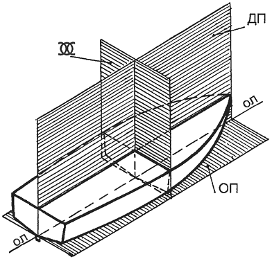
Basic planes necessary for constructing a theoretical drawing of a boat hull
Having dealt with all the theoretical issues, we move on to practice. Collecting all the tools and materials and preparing them for work is the final part of the preparation, so this process must be treated with special care.
Consider the list of tools and instruments that will be needed during assembly:
- It is best to take wood that has lain for at least a year in a dry place on a flat surface
. Boards that will serve as the main material. It is best to choose pine or spruce. It is perfect for such purposes due to its characteristics. The boards must be free of cracks and falling branches. Many people believe that the board should be completely free of knots, but this is a misconception. They won't do any damage to the boat if you hold on tightly. You can check this by hitting them with a hammer or even a sledgehammer. A crash test like this immediately gives many people an understanding of the whole situation. In addition, it is best to take wood that has lain for at least a year in a dry place on a flat surface. - Polyurethane glue.
- Nails. You will need nails of different lengths, in large quantities. But you need to understand that often they can be replaced with screws.
- Screws. Like nails, they should be of different lengths.
- Screwdriver and drill. Any screwdriver will do, but you need a drill that is not very powerful so that it does not split the wood. You can even use a hand drill. It is not recommended to replace a drill with a hammer drill.
- Jigsaw.
- Sandpaper.
- Roulette.
- Tow.
- Water-repellent paint (in large quantities).
- Brushes for applying paint.
- Resin. It can replace glue, although working with it requires more attention and skill.
- A syringe for applying glue to hard-to-reach places.
- Paracord It will be needed to give the sides the required shape. Can be replaced with other dense ropes that can withstand heavy loads.
- Sheets of metal (can serve as an excellent bottom for a boat, and can also be used to fasten some parts together well).
- Antiseptic. Needed to impregnate wood.
- Varnish. It is advisable to use high-quality yacht varnish.
This is the main list of what will be useful during assembly. In addition, other tools may be useful in the process. For example, a hacksaw, a hammer, clamps, etc.
Selection of boards for lining the bottom of a punt boat
Boat hull
Manufacturing Features
There are really a lot of features, so let's look at them in detail:
- Working with wood. The first and main feature is the ability to work with wooden structures and wood in particular. You need to understand which boards are best to choose, how to bend them correctly, what loads a particular material can withstand. Before starting work, it is best to prepare and read books on woodworking. They are very easy to find and are freely available on the Internet.
- Selection of materials for assembly. In addition to wood, you must immediately decide on other materials that will help hold the boat together and protect it from leaks. They must be suitable for the material that has been chosen and interact well with it.
- Assembly location. Manufacturing will definitely require a lot of space and time. For professionals, manufacturing and assembly can take from 4 to 10 days, depending on the complexity. A beginner will need several times more time. This is why it is important to choose a dry and comfortable place.
- Tools. To facilitate and speed up the process, you will need a number of tools (which we will look at later). In addition, it is advisable to have an extra pair of hands during some stages of assembly.
These are the main features you need to know, but as you progress, you will likely encounter others.
Drawing of a boat from boards for self-production
Deciding on the sizes
One of the most important stages in the planning stage. The size determines the capacity, load capacity and weight. It is very important to maintain the correct dimensions so that the boat is stable on the water.
They can be changed at your discretion, but within reason:
- Length of the entire structure. The length can vary from two to four meters. If the vessel is designed for one, then the length should be 1.8 - 2.5 meters. Two people – approximately 3 meters. Three people – 3.5 – 4 meters. A boat 3-4 meters long can easily support up to 5-6 people; the issue here is more about comfort.
- Width. Also one of the main criteria. Average widths are 1 – 1.5 meters. The greater the width, the more stable it is wonderful. On the other hand, the greater the width, the less maneuverability. It is necessary to find a middle ground. It is different for everyone depending on the person’s body, the load that will be transported, as well as the length of the entire structure.
- Board height. The average and recommended side height is 50 centimeters. Again, you can make it either higher or lower, depending on your desire.
It is based on these dimensions that it will be necessary to make all the details in the future. It is difficult to determine these dimensions by eye, so it is best to make a drawing for clarity.
Moving on to the drawings, we must immediately say that it is not necessary to have a talent for drawing. At the moment, a drawing can be made without having such skills online on the Internet. You can make a three-dimensional model that will meet all the requirements and desires.
In the drawing, in addition to the main dimensions, you must immediately determine the dimensions of other, smaller, but no less important parts. It is best to make drawings for them separately, so that you do not have to adjust them in the future.
Basic planes necessary for constructing a theoretical drawing of a boat hull
Required materials and tools
Having dealt with all the theoretical issues, we move on to practice. Collecting all the tools and materials and preparing them for work is the final part of the preparation, so this process must be treated with special care.
Consider the list of tools and instruments that will be needed during assembly:
- It is best to take wood that has lain for at least a year in a dry place on a flat surface
. Boards that will serve as the main material. It is best to choose pine or spruce. It is perfect for such purposes due to its characteristics. The boards must be free of cracks and falling branches. Many people believe that the board should be completely free of knots, but this is a misconception. They won't do any damage to the boat if you hold on tightly. You can check this by hitting them with a hammer or even a sledgehammer. A crash test like this immediately gives many people an understanding of the whole situation. In addition, it is best to take wood that has lain for at least a year in a dry place on a flat surface. - Polyurethane glue.
- Nails. You will need nails of different lengths, in large quantities. But you need to understand that often they can be replaced with screws.
- Screws. Like nails, they should be of different lengths.
- Screwdriver and drill. Any screwdriver will do, but you need a drill that is not very powerful so that it does not split the wood. You can even use a hand drill. It is not recommended to replace a drill with a hammer drill.
- Jigsaw.
- Sandpaper.
- Roulette.
- Tow.
- Water-repellent paint (in large quantities).
- Brushes for applying paint.
- Resin. It can replace glue, although working with it requires more attention and skill.
- Syringe for applying glue to hard-to-reach places.
- Paracord It will be needed to give the sides the required shape. Can be replaced with other dense ropes that can withstand heavy loads.
- Sheets of metal (can serve as an excellent bottom for a boat, and can also be used to fasten some parts together well).
- Antiseptic. Needed to impregnate wood.
- Varnish. It is advisable to use high-quality yacht varnish.
This is the main list of what will be useful during assembly. In addition, other tools may be useful in the process. For example, a hacksaw, a hammer, clamps, etc.
Selection of boards for lining the bottom of a punt boat
Manufacturing process
Let's move on to the most interesting part, the manufacturing process. Let's present it in the form of step-by-step instructions.
There is no room for haste or shortcomings, so we do everything extremely carefully and clearly:
- A pre-prepared part according to the drawings, which will serve as a tailgate, should now fit perfectly in dimensions.
The first stage of manufacturing all parts according to the drawings and their preparation. This includes preparing the sides. Two wide ones (which will serve as sides) need to be prepared by removing dangerous places from them. For this you will need a file and sandpaper. - Next, on one side of each board we saw off the edge at an angle of 45 degrees. We chamfer the silted ends so that when they touch, both boards fit perfectly together and have no gap. This will be the bow of the boat.
- Now you need to secure them in this position. To do this, use a triangular block and place it tightly on the inside of the joint. If necessary, we adjust everything and tightly fasten the sides to this bar using nails or screws. To prevent these places from leaking, the edges of the contacting boards must first be soaked with an antiseptic, and then with resin or glue, and only then fastened together.
- Now the sides need to be given the required shape. You need to take paracord and tie it around the sides giving it the desired shape. For everything to work out, we install spacers inside, which should be the same width as the width of the future vessel. It’s difficult to do everything yourself at this stage, so an extra pair of hands won’t hurt.
- Having given the sides a shape, you can move to the back of the boat. The pre-prepared part according to the drawings, which will serve as a tailgate, should now fit perfectly in size. We firmly attach it to the sides using glue, as well as nails or screws.
- Now that the base of the boat is ready, you can move on to creating the bottom. It can be made from sheets of metal or wood.
- In the case of metal, we cut out a sheet that will be several centimeters wider in size than the bottom of the boat, and attach it to the sides. It is important to understand that it is at these joints that leaks most often occur. Therefore, for fastening, we do not skimp on glue or resin at the joints, and drive screws or nails at a distance of 1.5 - 2 cm from each other along the entire contour. For reliability and better protection against leakage, tow can be used at the joints. Using a hammer, we bend the metal protruding at the edges tightly to the sides.
- In the case of a wooden bottom, everything is a little more complicated. It is best to make it from one wide board that can cover the entire bottom at once. We give it the necessary shape and treat it in the same way as in the case of metal.
- At this stage the boat is almost ready. Now you need to treat it with an antiseptic, eliminate all possible gaps through which water can flow, and paint it with several layers of water-repellent paint. Next we coat it all with yacht varnish. Before applying each new layer, the previous one must be allowed to dry completely.
- The last stage is interior finishing. You can install benches, footrests and other “chips” that the designer desires.
Boat testing
After creating and assembling the vessel, we move on to testing it.
You can test the boat in different ways, but the best number of stages is:
- The first waterproof test can be done in the yard. To do this, we turn the boat over and place it on some kind of support (chairs, benches, table). Next, pour a large amount of water on it. To do this, it is best to use a hose and “water” for 5-10 minutes. After this, the boat can be turned over and checked to see if water has gotten inside.
- Now, knowing that the schooner does not allow water to pass through, you can proceed to access to deep water. More precisely, try it in action. It is strongly recommended not to swim to great depths for the first half hour, because if something is done wrong and the boat begins to quickly take on water, it is much easier to get it out of the shallows.
It is strongly recommended not to swim to great depths for the first half hour.
Blitz tips
Let's look at a few tips that may be useful to a beginner in the difficult task of designing and assembling:
- When assembling, do not spare materials. For example, when fastening the sides to the bottom of a boat, it is worth spending extra time, but carefully going over all the joints with glue or resin. It will be very difficult to correct such errors in the future.
- Do it with reserve. Excess parts of everything can be removed, for example, by sawing off a block in the bow of the boat. This also applies to all other details.
- Before using large nails or screws, it is advisable to make holes for them using a drill. This will prevent cracks from appearing.
- Don't skimp on materials. The higher quality the wood, the longer and better it will last in the future.
Photo tips on how to make a boat with your own hands
Note!
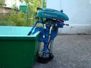
Do-it-yourself boat motor - tips for beginners, projects, drawings and step-by-step description of the construction of the main components and elements (video + 120 photos)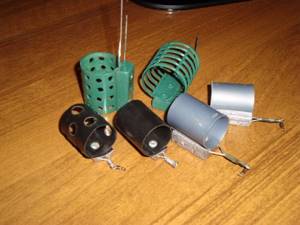
Feeder for winter fishing - secrets of use and techniques for feeding fish in winter (115 photos)
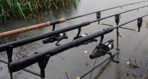
Bottom gear - the most effective types of equipment and features of casting techniques (95 photos and videos)
Read here Balda for perch - gear and tips on how to catch perch correctly. 115 photos and videos of perch fishing
Help the project, share on social networks 
0