Which material to choose
What the screw will be made of should be chosen depending on its further purpose. For example, solid bars are ideal for making propellers intended for powerful engines (about 15-30 hp)
If you consider yourself an experienced craftsman, then an aircraft plywood blank with a large number of layers is suitable for you. But amateurs should not start with it, because this specimen is very fragile and can form uneven surfaces.
PROPELLER: HOW TO CALCULATE IT?
Beginning designers still have a need for a simple and reliable theory for calculating the power plant of a homemade aircraft (USA) or snowmobile. The necessary information is scattered across various magazines and special books. In addition, a comparison of published calculation methods shows that sometimes they give inconsistent results both due to different initial principles and due to different values of coefficients in the formulas. Our presentation uses the simplest physical laws and statistical data on several dozen successfully flown UAVs, which significantly increases the reliability and practical significance of the formulas given below.
What should the propeller thrust be for the aircraft to take off easily? - this is the main question that the designer who begins to design the SLA must first solve. Many failures and bitter disappointments occurred only because this issue was left for later and was not given paramount importance.
The propeller thrust F required for takeoff is determined by only two parameters: takeoff weight G and the minimum (in takeoff mode) lift-to-drag coefficient K0:
F=G/K0
Take-off weight is understood as the sum of the weights of the empty aircraft, the pilot, gasoline and luggage (cargo), and the aerodynamic quality is equal to the ratio of the lifting force of the wing to the drag force.
Beginning designers usually greatly overestimate the K0 value of their future device compared to what is actually achievable, and also tend to underestimate G, so for the success of the project you need to be self-critical and make extremely tough estimates.
According to the literature data on the built SLAs, it turns out that it will be correct if during design we take K0 = 3. This is especially true for the SLAs that have the simplest “rag” wing with a single skin.
Thus, an easy takeoff will be ensured by a power plant that creates thrust F = G/3. For example, with G = 210 kg, the required thrust is 70 kg. Of course, lifting off the ground can occur with less thrust, but the speed of vertical ascent will be small or in general the device will only fly at a low altitude when the ground effect is in effect. The latter slightly increases K0, and when designing, for example, an ekranolet, you can take K0 = 4.
As for snowmobiles, for them the role of the coefficient of aerodynamic quality is played by the value inverse to the coefficient of friction of skis on snow Ktr. According to V.G. Ostashov and L.B. Sandper, Ktr increases with increasing speed and reaches a value of approximately 0.2 at V = 50 km/h (relatively small air resistance is also taken into account here). Therefore, for the “airplane” quality factor, the value Ko = 1:0.2 = 5 can be taken. If poor gliding is expected, then this indicator should be lowered to 4.
How to obtain the required propeller thrust?
Thrust (we are talking about a two-blade fixed-pitch propeller) primarily depends on the following parameters: motor power N, diameter D and propeller rotation speed n. Theoretically, these parameters are related by relationships that are easy to obtain from considerations of physical dimension:
where ρ is the air density, k1 and k2 are the dimensionless thrust and power coefficients. From here, after simple transformations, the following two formulas are obtained:
where a and b are some coefficients.
The values of a and b were determined by the author as a result of statistical processing of data on the power plants of approximately forty SLAs. These data are given in the technical report on the SLA-87 review-competition (published by the Siberian Scientific Research Institute of Aviation, Novosibirsk, 1990). It turned out that on average a = 7.5±1, b = 1.6±0.2.
Deviations from the average values are given with a 90 percent probability, that is, 90 percent of the “calculated” SLAs had values of these coefficients within the range of 6.5 - 8.5 and 1.4 - 1.8, respectively. Thus, the propeller thrust and its rotation speed should be calculated using the formulas:
Here and below, the traction force F is expressed in kg, the motor power N is in hp, the propeller diameter D is in m, the propeller rotation speed n is in thousand rpm.
From formula (1) it is clear that the propeller thrust is determined by the product of the motor power and the diameter of the propeller. Consequently, the required thrust can, in principle, be obtained from a low-power motor if you use a large-diameter propeller and at the same time, according to formula (2), reduce the propeller speed.
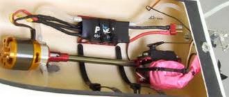
The calculation of the power plant is carried out depending on what the designer has to create his device. Usually they start from what kind of engine they have - a motorcycle, a boat, a snowmobile, a motor pump, a diesel launcher, a chainsaw, and, at best, a special aircraft engine for a small aircraft. Therefore, first you need to find out whether the existing one is suitable for the device being designed?
Let, for example, there be a motor with actual (or rated, if it is new) power N = 10 hp, and the required propeller thrust is 70 kg. The question is, what should the diameter of the propeller and its rotation speed be in order to obtain the required thrust? The screw diameter is found from formula (1):
and the rotation speed is according to formula (2):
Thus, this motor will require the use of a very large (by the standards of an SLA or amateur snowmobile) propeller, which must also rotate at a very low speed, which, in turn, will lead to the need for a complex multi-stage gearbox, since the crankshaft speed of the motor is usually are 5-6 thousand rpm. The result will be a bulky and heavy power plant, so it is better to abandon such a motor.
When designing, you can also proceed from dimensional considerations. For example, let’s say, according to the design dimensions of the power plant, the propeller diameter should not exceed 1.5 m. The required propeller thrust is 70 kg. What should be the power and speed of rotation of the propeller? From formula (1) N = 19 hp, and according to formula (2) n = 2.172 thousand rpm.
Some boat motors (Privet-22, Moskva-25, etc.) and motorcycle motors (IZH-Jupiter, etc.) may be suitable for this option, and a gearbox must be used that provides the calculated propeller speed.
Making a gearbox under amateur conditions is a complex and not entirely reliable task, so you should strive to use a factory-made gearbox. For example, a motorcycle engine already has a suitable gearbox - in the form of a chain or gear transmission from the crankshaft to the clutch. Let, for example, there be a new IZH-Yu-5 engine with N = 24 hp, and its gearbox n = 2.3 thousand rpm. The required thrust is still 70 kg. From formulas (1) and (2) we find that these motor and gearbox will provide thrust F = 82 kg (which is even significantly more than required, which is always useful) with a propeller diameter D = 1.52 m.
It should be noted that if there is a very powerful motor, and the diameter of the propeller is small, for example, D = 1 m, then it is impossible to obtain very high thrust. This is explained by the limitation of the linear speed of the tip of the blade, which should not exceed 220 m/s - at higher speeds the sound barrier appears and the efficiency of the propeller decreases. Therefore, its rotation speed must be limited by the condition n<4.4
For example, with D = 1 m, the propeller rotation speed should not exceed 4.4 thousand rpm. With these values of D and n, the power consumed by the propeller from the motor will be 21 hp, and the thrust will be about 57 kg.
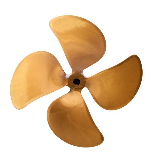
It may happen that the existing motor and gearbox can provide thrust that is only 10-15 percent less than required. In this case, you can still get the desired thrust if you replace the 2-bladed propeller with a 4-bladed one. Theory shows that such a replacement (with the same N and n) leads to an increase in thrust by 15 percent and a decrease in the diameter of the propeller by the same 15 percent.
Finally, to increase traction, you can use the “propeller in a ring” design, but it must be taken into account that a cone-shaped ring around the propeller will make the power plant more bulky and make it a little heavier. More information about the “screw in a ring” scheme can be found in the book by V.G. Ostashov and L.B. Sandler “Gliding Amphibious Snowmobiles”, Novosibirsk, 1991.
Propeller geometry
A simplified calculation of the propeller consists of finding only the installation angles φ (R) of the blade sections depending on their distance (R) from the axis of rotation of the propeller. The thrust force, the diameter of the propeller and the speed of its rotation must be determined in advance. It is advisable to calculate the propeller for the take-off speed of the UAV, which is found by the formula:
where G is take-off weight, kg; ρ = 1.25 kg/m3 - normal air density; Su = 1.4 - average wing lift coefficient for SAL in take-off mode; S—wing area, m2. For example, with a weight G = 210 kg and an area S = 15 m2, we obtain a speed V = 46 km/h.
In the case of an aerosleigh propeller, the “cruising” speed of the aerosleigh should be used as the calculated V.
Diagram explaining the definition of angles α, β and φ: P.v.
— plane of rotation of the screw; W is the linear velocity vector of the rotational movement of the blade in a given section; V is the vector of propeller forward speed (SLA flight speed); U is the velocity vector of the air flow incident on a given cross-section; B and T are the width and thickness of the workpiece for making the screw. The profiles of the propeller blade sections are assumed, as usual, to be plano-convex (the flat side is the working side, the convex side is the rear). Then the installation angle φ (R) will be the angle between the flat side of the blade in its given section and the plane of rotation of the propeller. The figure shows that the installation angle is greater than the angle of attack α by the angle β, determined by the formula:
Here V is expressed in m/s, n in thousand rpm, R in m.
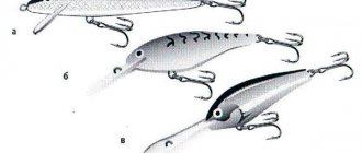
Calculation using the given method also assumes knowledge of the limiting angle of attack, above which the flow stalls in a certain section of the blade and the propeller stops working well. The magnitude of this angle depends on the section profile used. According to the mentioned book by Ostashov and Sandler, we can recommend the RAF-6 profile, which has a maximum angle of attack of about 18°.
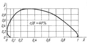
RAF-6 profile. The coordinates of the real profile are found using the formulas: y = ̅у • с;
x = ̅х • b, where b is the profile chord (blade width), c is the maximum profile thickness in a given section of the blade. The propeller is made from a rectangular wooden beam (spruce, birch, etc.) with length D, thickness T and width B. In this case, the width (chord) of the blade B(R) in any section will be equal to B/cos φ (R). To simplify the calculation, you can take B(R) = B = const, since the installation angles φ (R) are relatively small (8-30°) and therefore cos φ (R) = 1. The ratio of the maximum profile thickness (c) to its chord , that is, c/B is taken within the range of 8-30 percent with a smooth increase from 8 at the end of the blade to 30 percent at the propeller hub.
To find the angle φ in any section, it is necessary to separately calculate the angles α and β and then add them. The angle of attack α (R) can be found from the condition of constant specific thrust ρ along the blade span in its design section:
where Cy(R)=4.8 [α(R)+0.0175] is the coefficient of “lift” (that is, the thrust of a given section), associated with the angle of attack α(R), expressed in radians, and U2(R )=104n2R2+V2, m2/s2 - the square of the speed of the air flow flowing onto a given section of the blade (for an observer, as if rotating with the propeller). The concept of “specific thrust” is similar to “wing load” and shows how many kilograms of thrust fall per unit area of the design section of the blade. Specific thrust in this case is the same as air pressure, and condition (4) then means that there are no pressure differences across the blade span, which should theoretically increase the efficiency of the propeller.
Taking this into account, from (4) we obtain the following equation for calculating angles of attack:
Here ρ is expressed in kg/m2, n - in thousand rpm, R - in m/s.
Due to the existence of a limiting angle of attack, condition (4) cannot be satisfied on the entire blade, but it can be satisfied on half of its span - from the end, where R=D/2, to the section, where R=D/4. Consequently, the calculated section of the blade will have a length ΔR=D/4 and an area ΔR•B=DB/4. Then the specific thrust of a 2-blade propeller is found by the formula:
Let's consider a specific example: determine the installation angles of the sections of a screw with a diameter of D = 1.5 m, which at n = 2.3 thousand rpm, B = 0.12 m, V = 15 m/s and a maximum angle of attack of 1 8 ° should create a thrust F = 78 kg.
First, using formula (6), we obtain the specific thrust ρ = 867 kg/m.
Taking into account these values of ρ, n and V, we reduce formulas (3) and (5) to a form convenient for calculations:
Angles α, β and φ = α + β are calculated for the following values of R: 0.75 (end of the blade); 0.7; 0.6; 0.5; 0.4; -0.375 (end of the calculated section). We record the results in the table:
| R, m | 0,75 | 0,7 | 0,6 | 0,5 | 0,4 | 0,375 |
| α, deg. | 4,45 | 5,25 | 7,5 | 11,2 | 17,8 | 20,4 |
| β, deg. | 4,90 | 5,30 | 6,2 | 7,4 | 9,2 | 9,8 |
| φ, deg. | 9,35 | 10,6 | 13,7 | 18,6 | 27,0 | 30,2 |
As you can see, the maximum angle of attack of 18° is reached at the end of the calculated section, approximately at R = 0.4 m. If this had not happened, then the calculations would have to be repeated with a different value of blade width B, changing it in the appropriate direction compared to the original the accepted value is 0.12 m.
Determination of installation angles on the remaining section of the blade from R = 0.4 m to R = 0.1D = 0.15 m is carried out using the formula:
and for R=0.3; 0.2 and 0.15 m we obtain, respectively, the following values of the angle φ, degrees: 30.0; 35.8 and 41.2.
It should be noted that in the second section there is no particular need to obtain large installation angles, since the required thrust is already provided in the first design section. Therefore, based on the convenience of manufacturing the screw, it is possible to take φ(R) within 27–30° at R = 0.4...0.15 m. This will significantly reduce the thickness T of the workpiece (wooden beam), since T = B tgφmax. For example, at an angle φmax = 30° we have a thickness T = 12 tg30° = 6.9 cm, but at φmax = 41.2° we have T = 10.5 cm.
The given method for calculating the screw is not the only possible one. For example, installation angles are often calculated based on the condition of constant screw pitch H:
It is interesting to compare how different the installation angles calculated using this “step-by-step” method will be from the values found above. In the example we considered, V = 15 m/s or 54 km/h, n = 2300 rpm and for the propeller pitch according to these formulas H = 0.704 m, according to which the following values of the installation angles are obtained:
| R, m | 0,75 | 0,7 | 0,6 | 0,5 | 0,4 | 0,375 |
| φ, degrees | 8,5 | 9,1 | 10,6 | 12,6 | 15,6 | 16,6 |
From a comparison with the previous table it is clear that good agreement between the values of φ is observed at large R, that is, at the end of the blade. When R decreases, a significant difference arises - using the “step” method, the twist of the blade is less than using the “traction” method (by twist we mean a change in φ as R changes).
Of course, the correctness of the calculation of the propeller can ultimately only be shown by its traction tests. The “thrust” calculation method has an advantage due to the physical clarity of its fundamentals, in particular, a clear understanding of the role of blade width B: when it changes, the specific thrust also changes, and accordingly the angles of attack and installation angles will be different. In the “step” method, the width of the blade does not affect the installation angles in any way.
In conclusion, it should be noted that a single propeller built according to calculations can only in rare cases give the desired result. Therefore, several screws with different mounting angles should be made, and then the best one should be selected during testing.
B. KALEGANOV
We recommend reading
- ALL-TERRAIN CLIMBER Every time I carried bulky geophysical equipment across mountain glaciers, I dreamed of an all-terrain vehicle. Finally it was received. And here we are on an amphibious tracked vehicle against the snow-capped mountains......
- SWEDISH SPEAR Sweden was and remains one of the few countries in the world capable of independently creating first-class aircraft. The combat aircraft of this Scandinavian country have always been distinguished...
Instructions
So, how to make a propeller with your own hands? The process of creating a propeller looks like this:
- First you need to work on the templates, namely: 1 template for the top, 1 for the sides and 12 templates for the blade in profile.
- Plane the screw blank according to the dimensions on all four sides and draw the axis lines and contours of the side view template.
- Remove excess wood. First you do this with a hatchet, and then with a plane and rasp.
- Now place the blade template on the workpiece and secure it with a nail in the center of the sleeve for a while, then trace it with a pencil.
- Rotate the template 180° and trace the second blade. Excess wood can be removed using a fine-tooth saw. This work should be done carefully and not in a hurry.
- Remove the wood without haste, making small and short cuts.
- The screw must be brought to readiness using a plane and rasp and checked in the slipway.
- In order to make a slipway, you need to look for a board that is the same length as the screw size, and also allows its thickness to make transverse cuts of 2 cm in order to install templates. To make the central rod of the slipway you will need solid wood. And its diameter should be the same as the diameter of the hole in the screw hub. The rod should be glued to the surface of the slipway at an angle of 90°.
- Put the propeller on and see how much wood needs to be cut to get the blades to fit the profile templates.
- Once the bottom surface of the screw begins to match the templates, you can begin finishing the top surface. This operation is very important, since the quality of the resulting screw is based on it.
For beginners, it is not uncommon for the blades to not match in size. For example, one turned out thinner than the other. But to make the correct propeller, you will have to achieve equal size by reducing the thickness of the other blade. Otherwise the propeller will not have balance. Small mistakes can be easily corrected. For example, stick small pieces of fiberglass or smear with small sawdust mixed with epoxy resin.
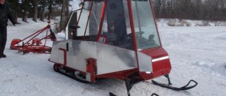
Making snowmobiles
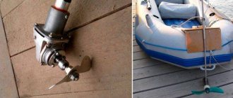
Many may object and offer to buy a branded snowmobile. However, this transport has serious drawbacks. The main one is the too high price, which not everyone can afford. Also, a snowmobile for ice fishing is dangerous, especially in early autumn or late spring. Its considerable weight does not allow it to travel on thin ice, where light sleds can easily pass on skis. Often a propeller-driven unit is installed on a boat. This version of the snowmobile is considered the most reliable, which can be safely used all year round and on any ice.
To build a snowmobile you will need the following tools:
- Welding machine.
- Electrodes.
- Mask.
- Bulgarian.
- Drill.
- Drill.
- Spanners.
- Hammer.
Engine selection
The most complex and most expensive unit is the motor . For a light sled for one person, you can install a small motor from a saw. But its low power will not allow you to drive fast enough. In addition, such engines have a short service life. It is best to choose a more powerful motor from a motorcycle. With such an engine, the sled in the snow will develop very good speed even with additional load.
Air propeller
The snowmobile moves with the help of a propeller. It must match the engine parameters. Otherwise, the motor will start to overheat or will not work at full power. This is a rather complex unit that is very difficult to make at home. If you build it with your own hands, it will take too much time. On top of that, serious knowledge of aerodynamics is required. Therefore, it is better to purchase a propeller in a store.
Frame assembly
To build the frame you will need the following materials:
- pipes,
- clamps,
- bolts,
- nuts,
- washers.
The easiest way to make a snowmobile is with three skis. This is the most common method, where the cost of material and construction time will be the lowest according to calculations. For these purposes, a triangular frame is made, which must be very strong. Because all the units will be attached to it. The structure will be light and durable if it is made of metal pipes. Craftsmen often make a frame out of wood. And although this is not the strongest material, it has one advantage. If for any reason the snowmobiles fall through the ice, they will still remain afloat.
Although this is the easiest option, for reliability and durability when building a sled, it is better to use iron pipes. First, you need to draw a drawing by hand and indicate the dimensions of the parts. In this case, it will be much easier to calculate the material consumption and correctly cut the pipes for the frame. First, they are laid out in a triangle on a flat floor. And the ends are connected by welding, and all seams are cleaned with a grinder. Then small bushings are cut from this pipe and welded to the ends of the frame. Three skis will be attached here. The two rear bushings are installed strictly vertically, and the front one for the steering mechanism is slightly inclined.
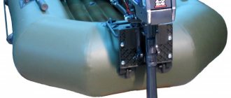
Engine Installation
Since snowmobiles use a propeller, the motor will have to be raised a considerable distance from the frame. To do this, you will first need to prepare two arched racks . They are easy to make from the same pipes that were used in the previous construction. One rack is attached by welding to the rear frame tube. And for the second, they make an additional crossbar inside the frame. When this work is completed, you need to install a mounting saddle for the motor at the top. It is easy to cut it out with a grinder from the old frame of the motorcycle from which the engine was removed. Or construct such a device with your own hands.
Propeller guards
To prevent the propeller from touching coastal bushes or tree branches, a fence is installed on the snowmobile. It is easy to make from the same material that was used to build the frame. To do this, you first need to bend the pipe into a large ring. Then, using a welding machine, attach it to the bottom of the frame, and the sides to the arc-shaped motor mounts. Often an additional grille is installed on the protective ring. Although this solution reduces the propeller thrust, it significantly increases the safety of the propeller.
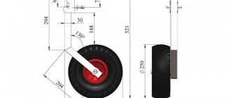
Ski construction
When building skis, almost all anglers prefer to use the simplest material - wood . This is the cheapest and most accessible option that is easy to process. When making snowmobile skis, wooden boards made of oak or birch are usually used.
First, they are dried well, and then the ends are sharpened and bent. To increase strength, the lower plane of the skis is covered with duralumin or iron. And a support hinge is installed on the upper part, which is easy to make yourself. To do this, first cut out a square plate of sheet steel along the width of the skis. Holes for screws are drilled along the edges, and a large nut or thick metal washer is welded in the center.
Skis are attached to racks, which are made from pipes of smaller diameter. It should fit easily into the bushings on the frame. A hole is drilled at one end for the cotter pin, and two nuts are welded parallel to the other, as if on a hinge. You will get a kind of fork, which is inserted into the frame bushing and pinned on top. Then the hinge on the ski is combined with the nuts at the end of the stand and secured with a finger or pin. It can be made from a thin metal rod or reinforcement.
Prop Balance
The already made screw needs to be balanced. That is, to ensure that the weight of the blades matches. Otherwise, when the screw rotates, shaking will occur, leading to serious consequences - all the most important components of your device will be destroyed.
But in practice, it is not uncommon for skilled craftsmen who do not wonder how to make a propeller to find that the weight of the blades varies. And this is even if all the manufacturing nuances are observed! There are many explanations for this: different specific gravity of the various components of the bar from which the screw is made, different layer densities and many other reasons.
But there is a way out of this situation. It is necessary to adjust the propeller blades according to the weight. True, there is one “but” here.