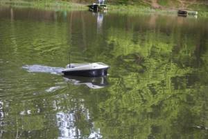
A report on how I made my own carp boat for delivering bait and equipment for almost FREE.
1. Overture 2. Body 3. Motor. Clutch. Deadwood. Screw 4. Water jet and rotary mechanism 5. Electrical circuit 6. Programming Arduino microcontrollers 7. Cover (deck) of the boat and controls on it 8. Unloading bait 9. Results 10. Video (14 parts)
Overture
Three years ago, under the influence of friends, I became interested in carp fishing. They taught me how to catch and told me all the secrets. The first carp have arrived. And then, one day while fishing, with an envious eye I saw a fisherman with a carp boat. I really liked this ship. I asked how much it cost - I really didn’t like it ($1000 “for a minute”). I googled it and it turned out that you can get it for $100, but that’s not it. In addition, a plan for a large-scale homemade project was brewing in my head in order to amuse myself and interest my son.
The first decision was made: to make a boat for delivering bait with your own hands. I looked through the forums on RC modeling, estimated the estimate - scratched my turnip. It came out to about $150 for components. Yes, and the task seemed too easy to me (woe to me, naive one).
The second decision was made: to make the most budget boat possible with your own hands, and ideally for free. Honestly, friends, not out of greed, but out of sporting interest.
So, a concept was developed: I decided to make a boat with DTMF control. This is when you call from one mobile phone (transmitter) to another (receiver), and when you press the keys, a “beep” of a different tone is heard. On the second phone (receiver), all that remains is to program the transformation of this “beeping” into different control commands depending on the received tone (one signal starts the motor, another stops it, the third turns it).
See how simple it is? I decided to convert the signal using the Arduino Uno board. We will consider this issue in detail in the Electronics section. Let's start with the body.
Operating principle
Bait boats operate very simply and clearly:
- The fisherman holds the control panel in his hands and sets the boat on the water.
- By pressing a button in the right place, the bottom lid in the loading hopper opens and the contents are poured into the water to attract a large catch. New models allow you to open the compartments simultaneously or do it separately.
- You can also add complementary foods in portions. The control range depends on the model: 150 – 500 m.
Frame
Initially, I planned to use the body from an old toy. The son (he had his share, so to speak) easily presented an old pirate frigate on wheels. But upon preliminary weighing of the proposed equipment (battery, motor, electronics, etc.), it turned out that the frigate did not have enough carrying capacity.
Unfortunately, I could not find a toy of a suitable shape at an adequate price in stores. And I decided to make the hull for my fishing boat myself. Again, after looking through many forums and articles, I decided that the material would be fiberglass and epoxy resin.
I started making the hull for the boat by building a blank, onto which I then planned to apply materials. I made the blank like this: I made a frame from fiberboard and cardboard. I simply attached it with hot glue to a sheet of fiberboard.
Then the compartments of the frame began to be filled with plaster (alabaster). A little life hack: add a little vinegar to the alabaster, and it will harden more slowly, but at the same time there will be intense release of gases, so do not forget to ventilate the room.
When the blank was dry, I corrected it a little and covered it with paper sketch, so that later it would be easier to separate it from the body.
The fiberglass I used is also called glass mat. The seller said that for curved shapes it is better to use it. Epoxy is the simplest.
And again a minute TB: You need to work in WELL ventilated areas. I'm not kidding. It’s not for you to mix a couple of drops in a matchbox. I bent over the hull of a fishing boat a couple of times while applying a layer of epoxy, and then for three days I couldn’t catch my breath and my head hurt.
I applied 2-3-4 layers of these. Previously, I was surprised by home-made workers: is it really impossible to count the two or three layers you applied. It turns out that while working, sometimes you have to overlap the layers, and sometimes you have to apply patches. Therefore, it is better to simply focus on the thickness of the case walls. On average, the hull walls of my fishing boat are about 3 mm thick. At this stage, the boat for delivering bait to the fishing point was called the “Pasta Monster”, because fiberglass fibers stuck out in all directions.
Next is the most tedious task - putty. I used this universal putty with fiberglass.
And also a lot of coarse sandpaper. Then the process is clear: rub, putty, rub, putty. And so on until you understand that this is the best thing you can do with your own hands.
When I removed the body from the blank, its weight was 1 kg 200 g. Which is pretty good for such rigidity and such load capacity.
I painted it when the water cannon was already in place (described in the next section). Painting was carried out in three stages: primer and two layers of “Yacht enamel PF-167” paint.
Preparation
The “boat”, like many other fishing accessories, is not difficult to build with your own hands. Before you start making such a useful and effective item, you definitely need to spend time on the preparatory procedures.
To make a high-quality fishing kit, a home craftsman who is interested in fishing will need to prepare the wood.
Alder or linden boards are best suited. Their optimal thickness will be 12 mm, and their width will be no more than 20 mm.
It is the wood material that will act as the basis of the working fluid of the structure. To connect all the fasteners and the cord, you need to purchase a special metal pin. Its diameter should be about 6 mm. Additional small spare parts will also be useful: washers and nuts, the thread and diameter of which correspond to the thread pitch and diameter of the metal stud.
For efficient loading of the main component of the gear, namely its keel half, special loads are used. These can be lead plates that are attached to the workpieces using self-tapping screws.
To process the upper parts of a product made from wood blanks, you need to purchase products that can effectively resist the process of water absorption. The most famous and effective component is simple drying oil. It can serve as a basis for further painting the “ship” with oil paints.
See about copters: Basic rules for assembling plastic airplane models
At the preparatory stage, it is strongly recommended to draw up detailed drawings and diagrams of the future homemade product. On the plan of such equipment for delivering bait, all dimensions of the main components should be indicated. The master will also need to purchase a special electric mechanism, which, together with the blade, will act as the engine of the “ship”.
Due to the presence of this component, the cost of homemade products increases noticeably.
When preparing to make gear, it is very important to stock up on the appropriate tools.
- You will need an electric jigsaw, which can be used to conveniently cut wooden parts according to templates.
- A small cutting machine is useful for rounding certain shapes and sanding homemade wooden components. This tool will also allow you to cut and trim metal studs.
- To drill holes and tighten the screws when fixing the weights, you will need a good screwdriver.
- Special drills for working on metal are selected in accordance with the diameter of the metal pin involved.
- Open-end wrenches are also useful for tightening nuts. They, like the fastening hook, must be selected based on the size of the nut used.
- When making a “boat,” you can’t do without a tape measure and drawing tools. They will be useful for marking the base material.
Having all the necessary spare parts, components, fasteners and tools, you can start making your own fishing “boat”.
Motor. Clutch. Deadwood. Screw
In this chapter, I’ll talk about what is most intimidating in boatbuilding for beginners - about the homemade deadwood (waterproofed shaft) and what is located on both sides of it: the propeller and the motor. Well, how to connect all this with your own hands so that it works reliably and flawlessly on a bait boat.
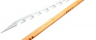
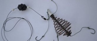
A homemade deadwood for a boat consists of the following components:
- The body is a thin-walled tube from an old refrigerator. External diameter 5mm, internal – 4.5mm. The edges had to be rolled out manually so that bearings with an outer diameter of 6 mm would fit on both sides.
- The shaft is a stainless steel rod with a diameter of 3 mm. On one side I cut an M3 thread for attaching the propeller.
- Bearings 3*6*2 mm. I ordered the bearings from the Chinese. In the photo there were bearings with boots, but upon arrival it turned out that instead of a boot there was only some kind of wire. The Chinese returned the money, but I decided to bet what I had.
- Oil seals. Their role is played by TO-220 insulating bushings (radio components, if anything).
The photo above and the video below show how the deadwood is assembled.
During operation, the oil near the bearings can heat up and become more liquid, so I decided to add more seals from simple 3/5 mm rubber rings. They are inserted directly in front of the bearing.
I used LITOL-24 as a thick lubricant. There are several nuances in filling the deadwood. You need to fill the deadwood housing with grease so that there is only grease inside, and not half grease, half water. To do this, the tip of the syringe is cut off to create a straight tube. The piston is removed. And such a tube is simply inserted into the barrel (or whatever you have) with lubricant to the very edge. Then the piston is inserted into the syringe, and only then do we remove the syringe completely filled with lubricant without air.
As for the clutch, I consider it my duty to inform you that you need to use the factory clutch. I checked many homemade rubber and metal options, but until I bought a normal coupling and aligned the motor in a plumb line, there were constant problems with reliability and runout.
When choosing a motor, I was dumbfounded by the prices, so I started looking for alternatives. I found the most powerful of the cheap ones - this is the 540-4065 electric motor.
I think that it was even possible to use a slightly weaker motor, but I can’t say so, since I haven’t tested my bait boat with weaker motors yet. Perhaps someday it will come to this, in order to increase the power reserve from a single battery charge.
I made the propeller myself from 1 mm thick brass. I cut out three identical blades in the shape of a pig's ear. And I soldered them to a bronze stand with an M3 thread. It turned out well, but I advise you to buy it, or you will have to make a device for proportional soldering of the blades.
After the first tests, it became clear that everything works well, but under one condition: if the sternwood has a fulcrum not far from the propeller. In my case, the screw is located at a considerable distance from the deadwood exit from the body. I decided to fix it relative to the body of the water cannon by soldering three MZ nuts to the deadwood and connecting the water cannon and the deadwood with screws.
Bait boat. What you need to know to avoid paying extra money.
I learned about the existence of such a feature as a bait boat ten years ago, and, of course, I became eager to have one someday.
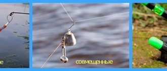
In advertising videos, sellers of this modern gadget vying with each other to praise expensive versions of ships with echo sounders, GPS, and even autopilots. Having looked at the wonderful properties of all these additional options, it is natural to want your boat to be no worse. If you’re not going to buy a cheap thing, then it should work “to the fullest”! That’s what I decided and I was disappointed. There was no one to tell me, and all these wonderful properties seemed too attractive to me. I, of course, will not consider premium class boats; they, frankly speaking, have exorbitant prices, comparable to the price of a good car. Maybe they will live up to all the charms described in the advertisement. I can’t say this for a simple reason: I have never seen such boats “live”, and, again, for obvious reasons. 1. It is desirable that it be a catamaran. Advantages: more stable on the wave, no rudder (which can jam), the ability to return the ship to the shore if one of the engines fails.
2. Two bunkers, with the possibility of delivering two gears. The advantages are clear - you save time on delivery and charging batteries.
3. Bottom unloading of bins. There are also “dump” types. In case of strong wind on a pond (which is not uncommon), such a bunker gives the strongest windage and does not obey the controls.
4. Echo sounder. A very good and necessary option. Economy class ships are equipped with absolutely unusable echo sounders, which show nothing except hull temperature and, at best, depth. It is better to purchase an echo sounder separately and install it yourself. Even inexpensive Chinese wireless echo sounders from Lucky
. Choose a boat that is sold in two versions - with and without an echo sounder; the hull will have a standard place for installing an echo sounder yourself.
5. Choose a boat with a 2.4 GHz
(there is also 433 MHz). Wireless fish finders operate primarily on the 433 MHz frequency, and the ship's control frequency can and will jam the sounder signal.
6. The “GPS” function or autopilot is not needed at all. The fact is that Russian standards require coordinate determination accuracy of up to 5 meters. Well, agree, feeding the fish five meters from the bait is pointless. It’s better to install beacons the old fashioned way.
Watch the video
about fishing with a bait boat on my
YouTube
Conclusion: of the options offered to you, boats with an echo sounder, GPS, etc. choose the simplest, which means reliable and cheap! The main thing is that it is reliable in controlling movement and dropping gear. You can install the options yourself if you wish.
Source
Water jet and turning mechanism
When designing my bait boat, I simultaneously correlated the size of the propeller, water jet cylinder and turning mechanism. After searching through many options, I decided on a deodorant bottle. The outer diameter of the balloon is about 42 mm, which is 4 mm larger than the circumference of the screw, and 3 mm. less than the diameter of the rotating mechanism, which will be described below.
After 153 measurements, with trembling hands, I cut a hole in the newly completed hull of my boat.
The water cannon was glued with hot glue. I made a hole to collect water. I decided to add a piece of aluminum perforation for additional rigidity of the cylinder, since the metal in it was very thin and easily bent with little effort.
Next, I attached the motor mount to the body of the bait boat. I did it this way: I attached a screw and a rigid coupling to the deadwood. To the coupling there is a motor fixed in the mount. After that, I set the boat in such a position that the sternwood took the most vertical position, while the motor was in free suspension.
It remains to apply a little glue to fix the correct position of the fastening, and after it cools, apply the amount of glue necessary for reliable fixation.
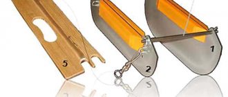
For the “rudder” in my fishing boat, I used a plastic jar of aquarium fish food. This jar, by the way, turned out to be divided into four parts by jumpers. All I have to do is carefully cut and mark everything for connection to the water cannon cylinder.
The turning lever is made of fiberglass 3 mm thick. I cut out an approximate shape, and then used a file and sandpaper to cut out a recess in the shape of a food can.
I took a knitting needle from an umbrella (2 mm thick) and threaded it into a waterproof boot for rods (33x12mm).
The end of the spoke was bent at an angle of 90 degrees and inserted into the SG-90 servo drive.
Principle of operation
Many fishermen, especially if they are new to this business, are interested in how exactly the so-called “ships” work. The operating principle of these devices is simple.
- Since this item has an asymmetrical design, it can easily move away from the side surfaces of the boat.
- A special weight is attached to the lower half of the “boat”, due to which the device can balance and be in the correct straight position.
- The tackle is attached to the main line at a short distance from the boat. This is done in such a way that the fishing line can be stretched, while the “boat” moves slightly to the side.
- As the process of wiring the device in question progresses, the complementary foods are gradually washed out. Due to this, the fish begins to swim closer to the desired fishing zone.
Electrical diagram
Everyone stays where they are and no one runs away. There is nothing to be afraid of. Below is a complete wiring diagram for a fishing boat. The diagram is large because it is detailed, but now everything will become clear.
Dotted lines highlight individual blocks. You may not use some of them at all, or replace some with an inexpensive purchased analogue. Just one circuit may seem complicated to you, but you don’t even need to understand it, and if you want, you can solder even what you don’t understand.
You can download and download the diagram in large format
So, control will be implemented from the keyboard in this way:
And in the table below you can see which pin on the Arduino Uno is responsible for which command. They are also afraid of the words pin, arduino, sketch; I’ll tell you everything in detail. The “Via:” column shows relays that are triggered when a specific phone key is pressed.
The DTMF decoder circuit is simple to implement, just 3 resistors and 1 capacitor. I was able to fit it all into a mini-jack plug.
Then it's a little more complicated. We will talk about the circuit of Arduino Uno, Arduino Nano and relays for Arduino boards. But still, the diagram is drawn in detail. And most of the connections are of the same type. For example, relay K1a-K6a is a relay for Arduino with a 5 V power supply. Each relay has three wires: +5 V, GND (2 wires for power) and signal.
When the phone receives a DTMF signal (for example, pressing the “3” key), it transmits it through the input pin A0 to the Arduino Uno board. There, this signal is instantly converted into a control signal, which is sent to the desired outgoing pin, for example, pin 6, and relay K3a is activated, thereby triggering the circuit to turn on the “Small Forward” mode.
The second board is Arduino Nano. It is used exclusively for turns. Input signals for Arduino Nano are outgoing signals from 7,8,9 pins of Arduino Uno. But before entering the Arduino Nano board, these signals are inverted by optical relay OR1-OR3 from logical one to zero, respectively from zero to one.
This complexity is due to the fact that the rotation sketch only works flawlessly in this order. That's all; The analysis of this circuit is completed.
Optorelays KR293KP9A were available. The opto-relay block looks like this:
Next, let's look at voltage regulators.
There are three of them in this block. The smallest and simplest is a 9 V stabilizer. It is called LM7809. It outputs exactly 9 volts, which powers the Arduino Uno and Arduino Nano.
Two regulators are used to set the comfortable speed “Full speed” and “Slow speed”. Firstly, for the “Full speed” mode, you can do without a regulator and simply power the motor in this mode with voltage from the battery. This will even increase the reliability of the system. Secondly, you can ask someone who is not afraid of a soldering iron to solder such regulators, if you have such a phobia. Or, in the end, explain to the radio store what power the motor is, what voltage you want to power it with, and they will select a regulator for you.
Motor control circuit:
I decided to make the motor control circuit using a relay. This is primarily due to the fact that I had them in stock.
I won’t lie. For unprepared people, this scheme is complicated. But I’ll at least tell you why it was created. Perhaps many will understand how it works.
Further, the same diagram is presented in two forms: the first is more convenient for installation, and the second is for analyzing how the interlocks work. The locks are made in such a way that when reverse is engaged, it is impossible to engage either small or full forward.
When the boat is sailing forward, it is impossible to turn into reverse. To change direction, you need to stop the boat by pressing the “0” key. The main idea of these interlocks is not to overload the electrical circuit. At the same time, on the go you can switch between low and full forward without any problems.
I placed relays and terminal blocks on the board. This is what the relay circuit installation looks like:
I soldered the outputs from the contacts and relay coils to the terminal blocks. Be sure to install diodes on the relay coils. It is not necessary to install blue varistors (2 circles).
According to the diagram, I connected the relay and power contacts to each other. This whole process is absolutely proprietary. I was chasing miniaturization. I did this. You can do it more cumbersome, but more neatly.
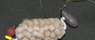
Unloading scheme
The principle of unloading is simple: we give a signal to the Arduino, the electric lock is activated, and the hopper with bait and equipment is released. The electric lock is a simple 24V solenoid from the paper feed in a laser printer.
To make the retraction force greater, I decided to increase the voltage from the battery to 30 V. This is done using a simple Chinese device MT3608, purchased on AliExpress.
Toggle switches, voltmeters and dimensions.
Here the diagrams delight the eye with their simplicity and accessibility. Dimensions can be achieved simply by attaching a bicycle light to the handle of a fishing boat.
I’ll finish the story about electronics with this emergency stop diagram:
It was created so that if there is an accidental loss of mobile communication while fishing, the fishing boat does not float over the horizon or into the reeds.
The principle of operation is simple: while the handset is off-hook and the phone (receiver) is in conversation mode, there is voltage on the headset microphone. It can be used to control an opto-relay, through the normally open contacts of which voltage will be supplied to the boat motor. If you end a call or if the network is lost, the voltage on the microphone disappears, the opto-relay opens and the motor stops.
Programming Arduino microcontrollers
Arduino, if anyone doesn’t know, is a microcontroller for the general public. Very accessible and simple. Roughly speaking: I connected it to the computer via USB, loaded it with a sketch (a program that says what the microcontroller will do) and everything is ready. I will not describe the process of installing drivers and downloading programs. Everything can be found on the Arduino website.
If you have any questions, the network is full of detailed descriptions of this process.
My bait boat uses two Arduino boards: one UNO and one NANO.
For Uno, in addition to the sketch, you will need libraries.
You can download and download the library HERE
The DTMF folder needs to be copied to the C:\Program Files\Arduino\libraries folder.
In the sketches themselves, after the “//” mark there are comments.
And here are the sketches themselves:
For UNO:
#include int sensorPin = A0; float n = 128.0; float sampling_rate = 8926.0; DTMF dtmf = DTMF(n, sampling_rate); float d_mags[8]; char thischar; int ledPins[] = { // Array for 10 PINS/relays. 2, 3, 5, 6, 7, 8, 9, 10, 11, 12 // 4-Pin, used by the library! }; void setup() { for (int i = 0; i <= 9; i++) { pinMode(ledPins , OUTPUT); // We make the entire array of ledPins OUTPUT. digitalWrite(ledPins , HIGH); // Set the entire ledPins array to HIGH. } } void loop() { dtmf.sample(sensorPin); dtmf.detect(d_mags, 506); thischar = dtmf.button(d_mags, 1800.); if (thischar) { digitalWrite(ledPins, LOW); delay(500); digitalWrite(ledPins, HIGH); } }
For Nano: // add a library for working with servos #include // for further work let's call 12 pins as servoPin #define servoPin 12 // 544 is the reference pulse length at which the servo should take the 0° position #define servoMinImp 544 // 2400 is reference pulse length at which the servo drive should take the 180° position #define servoMaxImp 2400 Servo myServo; void setup() { myServo.attach(servoPin, servoMinImp, servoMaxImp); // set the pin as the servo drive control output, // and also for the servo drive to operate directly in the angle range from 0 to 180°, set the min and max pulse values. pinMode(5, INPUT); pinMode(6, INPUT); pinMode(7, INPUT); myServo.write(1430); } void loop() { if(digitalRead(5) == HIGH) // Condition of the 1st button { myServo.write(1130); // Rotate servo left 45 degrees } if(digitalRead(6) == HIGH) // 2nd button condition { myServo.write(1430); // Return servo to center } if(digitalRead(7) == HIGH) // 3rd button condition { myServo.write(1730); // Rotate the servo to the right 45 degrees } }
Cover (deck) of the boat and controls on it
The material for the cover was fiberglass laminate 2 mm thick. I attached the hull of the fishing boat to a sheet of fiberglass laminate, traced the outline with a marker, and cut out the desired shape with a jigsaw.
The weight of the lid was 590 grams. For such rigidity this is quite a normal result.
Next, I placed the main power switch on the lid (it comes complete with a rubber cap),
I placed the power regulators and the toggle switch for the flashlight in a powder container, which I attached with “liquid nails” glue for complete waterproofing.
For the receiver phone and voltmeters I used an external junction box. It also houses the battery contacts for charging the battery. On the back side there is a connector for unloading.
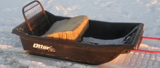
This is what a bait boat looks like with the lid installed, but without unloading: