The fishing process is becoming more technologically advanced and efficient. This is facilitated by the emergence of new devices that expand the capabilities of fishermen. A fish finder is one of the most common gadgets used in this field. Sensitive sensors scan the underwater space, providing the user with the necessary information through the screen. Today, an echo sounder for a smartphone on Android is becoming increasingly popular, the workflow of which only requires connecting a sensor. All recorded information is displayed on a mobile device without additional electronic devices.
What is a smartphone echo sounder?
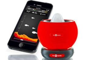
This is a type of portable sonar sensor that can be attached to a fishing line or a special rope. The traditional design of the device is the shape of a ball into which the transducer is integrated. You can only use an echo sounder with a smartphone from the shore, since on a boat, especially while moving, it will be impossible to ensure its reliable fixation. There are models for iOS and Android operating systems. In this case, the second option is considered, but increasingly manufacturers provide support for both systems.
It is important to emphasize the absence of wires in the communication system. If stationary transom models have a cable connection to the display, then an echo sounder that works with a smartphone transmits a signal via Bluetooth or Wi-Fi. There are also modifications with radio modules.
Three best models of Deeper echo sounders
| Specifications | |||
| Model | Deeper Pro+ | Deeper Pro | Deeper 3.0 |
| Price | RUB 19,900 | 16,900 rub. | 10,900 rub. |
| Reception range | 100 m | 100 m | 40-50 m |
| Size: | diameter 2.5″/ 6.5 cm | diameter 2.5″/ 6.5 cm | diameter 2.5″/ 6.5 cm |
| Compatibility: | From iOS 8.0 and Android 4.0 to the latest iOS and Android devices | From iOS 8.0 and Android 4.0 to the latest iOS and Android devices | |
| Case material: | Shockproof ABC plastic | Shockproof ABC plastic | Shockproof ABC plastic |
| Weight: | 3.5 oz / 100 g | 3.5 oz / 100 g | 3.5 oz / 100 g |
| Link: | wireless communication via Wi-Fi channel | wireless communication via Bluetooth up to ~140-160 feet / ~40-50 m Depends on the operating system and smartphone model. | |
| Depth limit, max./min.: | 260 ft (80 m) / 2 ft (0.5 m) | 130ft (40m) / 2ft (0.5m) | |
| Water temperature sensor: | Built-in | Water temperature sensor | Water temperature sensor |
| Temperature unit: | degrees Celsius / degrees Fahrenheit | degrees Celsius / degrees Fahrenheit | |
| Operating temperature: | -4°F to 104°F/ -20°C to 40°C | -4°F to 104°F/ -20°C to 40°C | |
| Battery: | lithium polymer; 3.7 V; rechargeable | lithium polymer; 3.7 V; rechargeable | |
| Power supply adapter: | 110 V / 240 V. Micro-USB. | 110 V / 240 V. Micro-USB. | 110 V / 240 V. Micro-USB. |
| Sonar type: | two-beam | two-beam | two-beam |
| GPS | Yes, creation of biometric maps of reservoir depth | No | No |
| Frequency: | 290 kHz (15°) / 90 kHz (55°) | 290 kHz (15°) / 90 kHz (55°) | 290 kHz (15°) / 90 kHz (55°) |
| Color: | black | black | black |
All 3 models of echo sounders have the right to life.
We dreamed of a floating platform, seven bass! It's almost a mini bass boat, collapsible and inflatable, ready to face beautiful waves and strong currents in all serenity! In addition to the basic waders, pumps and fins, you can customize your float as you wish to enhance the efficiency and comfort of your fishing experience.
Waders Even if you're not cold, waders are essential for a float tube. Neoprene Waders: Like wetsuits or surfing, neoprene waders have a thickness that can vary from 3 to 4.5 mm. The vast majority of neoprene waders have rubber boots as shoes: these models are necessarily prohibited for float tubes because the boots cannot fit into the fins. Thus, only a few brands offer neoprene slipper waders in the same material. Because of its thickness, neoprene offers true insulation, very useful for early and late season freshwater, similar to the fact that it is a little bulkier and can trap a fisherman.
Pro+ captivates with the ability to create and save a map of the area underwater
, which greatly helps the angler navigate fishing and choose the right place for feeding.
The Pro model has Wi-Fi.
Its signal is stable and does not depend in any way on the positioning of the phone, the reception range is up to 90 m.
Deeper 3.0
- this is a budget version, the cost is almost 2 times lower than that of the maximum Pro+, but it also has a basic set of the most important features, because the sensor used is exactly the same as the Pro+: depth measurement, the nature and topography of the bottom, the presence of fish, its size and depth.
Because they are lightweight, breathable waders offer true fishing comfort. All of them are equipped with 4 to 5 mm thick neoprene shoes to keep your feet in cold water. It is recommended to use a pair of booties, even very important, with waders for a perfect fit of the fins.
Choose a shoe boot size that matches your usual shoe size, boot boots that are cut wide and take into account the thickness of the neoprene shoe. Flippers The original concept of a float tube is based on human movement, so fins are essential for seamless progress.
How the device works
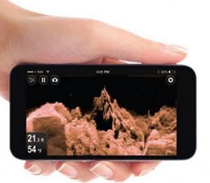
Despite the significant differences between portable wireless and stationary models, all echo sounders operate based on the emission of pulses, which are processed and presented to the user in a convenient form. The same smartphone, using a special application, will graphically reflect the bottom topography, show the depth and activity of fish - the specific set of information depends on the model. The main means of echolocation is the aforementioned transducer. This is an emitter sensor that sends signals to the bottom surface and receives reflected waves. During operation, the echo sounder and the smartphone can change interaction parameters depending on the conditions. In particular, the user can initially configure the communication properties himself, but high-tech models are able to automatically adjust, for example, the frequency of sending pulses. After the information appears on the smartphone screen, the user makes certain decisions to change fishing tactics. Such devices allow you to search for the most favorable places for fishing.
Do-it-yourself echo sounder for fishing
Homemade items from a washing machine motor:
1. How to connect a motor from an old washing machine through or without a capacitor 2. Homemade emery from a washing machine motor 3. Homemade generator from a washing machine motor 4. Connecting and adjusting the speed of a commutator motor from a washing machine - automatic 5. Potter's wheel from a washing machine 6. Lathe from an automatic washing machine 7. Wood splitter with an engine from a washing machine 8. Homemade concrete mixer
Homemade mini-echo sounder on Atmel ATMega8L microcontroller
And
LCD from mobile phone nokia3310
I present to your attention my author’s development - a homemade mini-echo sounder on an Atmel ATMega8L microcontroller and an LCD from a nokia3310 mobile phone. The device is designed to be replicated by an average-skilled radio amateur, but I think anyone can replicate the design. I tried to present the material in such a way as to give readers more useful information on the topic in an accessible form. I hope that repeating the design will bring you a lot of pleasure and benefit.
I will be glad to answer your questions/wishes/comments and help in repeating the design.
Best regards, Alex
Echo sounder, sonar - short for SOund NAvigation and Ranging. Echo sounders have been around since the 40s, and the technology was developed during World War II to track enemy submarines. In 1957, Lowrance released the world's first transistorized fish finder for sport fishing.
The echo sounder consists of the following main functional blocks: microcontroller, transmitter, emitter sensor, receiver and display. The process of detecting the bottom (or fish) in a simplified form is as follows: the transmitter emits an electrical impulse, the emitter sensor converts it into an ultrasonic wave and sends it into the water (the frequency of this ultrasonic wave is such that it is not felt by either humans or fish). The sound wave is reflected from an object (bottom, fish, other objects) and returns to the sensor, which converts it into an electrical signal (see figure below).
The receiver amplifies this returned signal and sends it to the microprocessor. The microprocessor processes the signal received from the sensor and sends it to the display, where we already see an image of objects and the bottom topography in a form convenient for us.
What you should pay attention to: the echo sounder draws bottom relief only in motion. This statement follows from the principle of operation of the echo sounder. That is, if the boat is stationary, then the information about the bottom topography is unchanged, and the sequence of values will consist of identical, absolutely identical values. A straight line will be drawn on the screen.
The first question that I am sure will arise from readers is “Why is such a small display used?” Therefore, I will answer it right away: this “mini-echo sounder” was developed at the request of a friend from what was at hand. And these available means turned out to be ATMega8L, a display from nokia3310 and some kind of emitter with the designation f=200kHz. You may also be asking, is it possible to remake the program/circuit for another, larger display? Yes. Theoretically this is possible.
My design differs from the echo sounders described in [1, 2, 3] by the use of a graphic LCD display, which gives the device advantages in displaying useful information.
The entire structure is assembled in the “Z14” housing. Power is provided from a 9V GP17R9H battery. The maximum current consumption is no more than 30 mA (in the author's version 23 mA).
Now about the capabilities of the echo sounder. The operating frequency is 200 kHz and is adjusted to the specific existing emitter. The ability to measure depths up to 99.9 meters is implemented in software. But I’ll say right away: the maximum depth that an echo sounder can “see” will largely depend on the parameters of the emitter used. At this time, my design was tested only on a reservoir with a maximum depth of about 4 m. The device showed excellent results. Whenever possible, I will try to test the operation of the echo sounder at greater depths, which will be reported to readers.
So, let's move on to the diagram. The mini echo sounder circuit is shown in the figure below:
The main functional blocks of the echo sounder: control circuit (that is, the ATMega8L microcontroller), transmitter, emitter, receiver, display, keyboard, battery charging circuit.
The echo sounder operates as follows: the microcontroller at pin PB7 generates a control signal (rectangular pulses log. “0”) with a duration of approximately 40 μs. This signal starts the master oscillator with an operating frequency of 400 kHz on the IC4 chip for a specified time. Next, the signal is fed to the IC5 chip, where the signal frequency is divided by 2. The signal from IC5 is fed to the buffer stage on the IC6 chip and then to the Q3 and Q4 switches. Next, the signal from the secondary winding of transformer T1 is fed to the piezoceramic sensor-emitter LS2, which sends ultrasonic messages to the external environment.
The signal reflected from the bottom/obstacle is received by the emitter sensor and fed to the input of the receiver, which is assembled on the SA614AD microcircuit in a typical connection (see Datasheet on SA614AD). The BAV99 diode assembly at the receiver input limits the input voltage of the receiver while the transmitter is operating.
The signal from the receiver is fed to a comparator on the LM2903 chip, the sensitivity of which is controlled by the microcontroller.
Next, the signal is processed in the microcontroller and displayed in the required form on an 84x48 pixel graphic LCD display.
The transmitter transformer T1 is wound on a K16*8*6 core made of M1000NM ferrite. The primary winding is wound in 2 wires and contains 2x14 turns, the secondary winding is 150 turns of PEV-2 0.21mm wire. The secondary winding is wound first. The halves of the primary winding must be “stretched” along the entire length of the core. The windings must be insulated from each other with a layer of varnished cloth or transformer paper.
Now the most interesting and problematic part: the emitter sensor. This problem was solved for me initially: I already had a ready-made emitter. What should you do? Option 1: purchase a ready-made sensor. Option 2: make it yourself from TsTS-19 piezoceramics.
When flashing the ATMega8L microcontroller firmware, set the fuse bits according to the picture below:
Complete information on manufacturing, configuration, firmware and instructions for using a mini echo sounder
look in the attached archive!
Power supply system
The lack of wires causes one of the main disadvantages of such sonars. The fact is that fishing is a long process, and the autonomy of wireless electronics is always limited to a few hours. The sensors are equipped with batteries with an average capacity of 500-1000 mAh. Although in standby mode the device can remain potentially ready for use for several days, the active operating format consumes energy in 8-10 hours. This applies to models with 700-800 mAh batteries. We are talking about average indicators, since the rate of reduction in battery capacity will also be affected by weather conditions. For example, a winter echo sounder for a smartphone consumes 15-20% more energy, which should be taken into account. Some manufacturers also provide several batteries in one set. Moreover, depending on the format of the battery, it may be possible to recharge it from a car cigarette lighter. In this case, you can ensure an almost non-stop scanning process by charging and changing batteries.
ECHO SOUNDER
V. Timofeev
The echo sounder offered to readers differs from those described earlier (for example, in the magazine “Radio” No. 12, 1973 and No. 10, 1981) in its greater measurement depth and the presence of only one power source. To receive signals reflected from the bottom of a reservoir, a separate piezoelectric transducer is used, which simplifies the circuit diagram of the echo sounder and greatly facilitates its setup.
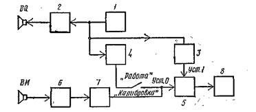
Rice. 1. Block diagram of the echo sounder
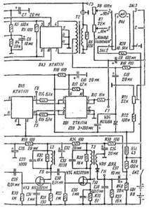
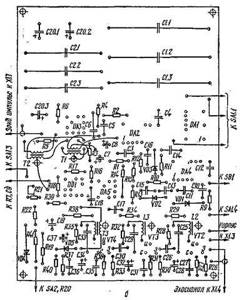
Rice. 2. Schematic diagram of an echo sounder
The device allows you to measure depths from 0.5 to 50 m with an error not exceeding 3...5%. The measurement range is divided into two subranges: up to 10 and up to 50 m. At each of the subranges, it is possible to check the functioning of the device using an internal generator of shifted pulses that simulate given depths. The echo sounder is powered from a 9 V source, the current consumption does not exceed 80 mA.
The block diagram of the echo sounder is shown in Fig. 1. Clock generator 1 starts the generator of 2 probe pulses, the generator of 3 paired pulses and the generator of 4 shifted pulses. Probing pulses are supplied to the BQ emitter, with the help of which they are converted into an acoustic signal propagating towards the bottom of the reservoir. Paired pulses are used to set trigger 5 to a single state. Trigger 5 is set to zero by the output signal of the receiving path formed by the microphone VM, which receives the acoustic signal reflected from the bottom of the reservoir, the radio pulse amplifier 6 and the detector 7. In the output voltage of the amplifier 6, in addition to the signal reflected from the bottom of the reservoir, there will be a pulse due to the influence of interference from the transmitting path to reception. The induced pulse has a more complex shape than the probing pulse and a longer duration. Its leading edge lags somewhat behind the front of the probing pulse. Therefore, it returns the flip-flop to the zero state immediately after it was set to the one state by the first paired pulse. The second paired pulse again sets the trigger to the single state, and the echo signal reflected from the bottom returns it to zero.
Thus, during each clock cycle, trigger 5 is set twice to each of the states, and two pulses will occur at its output. The first of them has a constant duration, which is determined by the time interval between the fronts of the first paired and induced pulses. The duration of the second will be proportional to the measured depth minus the constant distance that the acoustic signal travels in the water in a time equal to the interval between paired pulses. Returning the trigger to the zero state by an induced pulse leads to a systematic measurement error, which can subsequently be easily compensated since it is constant in both ranges. Indicator 8 measures the average trigger voltage, proportional to the measured depth.
The shifted pulse generator makes it possible to simulate pulses reflected from depths of 10 and 40 m. It is connected to the zero input of the trigger in the mode of checking the functioning of the device and its calibration. In this mode, there should be no echo signal in the receiving path, which is achieved by appropriate orientation of the emitter-microphone unit. In operating mode, this generator is disconnected from the trigger input.
The schematic diagram of the echo sounder is shown in Fig. 2, and the voltage diagrams are in Fig. 3. The clock generator is a self-oscillating multivibrator DA1. Its output voltage through the contacts of the switch SA1.1 is supplied to the monovibrators DA2 and DA4, as well as to the differentiating circuit C10R9 (and diode VD1). The oscillation period of the multivibrator is 66.7 ms, and the duration of the asymmetrical half-cycles is 13.3 and 53.4 ms, respectively, which is achieved by selecting the capacitances of capacitors C1 and C2. If the range switch SA1.2 is set to the “10 m” position, then a voltage is supplied to the inputs of the monovibrators and the differentiating circuit from pin 8 of the DA1 chip, in which the negative half-cycle has a duration of 13.3 ms (Fig. 3, diagram D1). Single-shot monovibrators are triggered by a negative drop in the input voltage, and the short positive pulse generated by the differentiating chain will be delayed relative to the beginning of the clock cycle by 13.3 ms, which is equal to the time of propagation of the acoustic signal to a depth of 10 m and back. On the “50 m” range, the input voltage to the monostables and the differentiating circuit is supplied from pin 14 of the DA1 microcircuit. In this case, the negative half-cycle has a duration of 53.4 ms, and the pulse generated by the differentiating chain will be delayed for a time equal to the arrival of the echo signal from a depth of 40 m.
Rice. 3. Voltage diagrams
The probe pulse generator consists of a DA2 CD-novibrator and a filling radio pulse generator with a power amplifier, made on a VAZ microcircuit. Single-shot DA2 generates a positive pulse (Fig. 3, diagram D2), the duration of which determines the operating time of the radio pulse generator. The required duration % is established by selecting the capacitances of capacitors SZ and C4. The radio pulse generator is made on one of the transistors of the DA3 microcircuit (pins 9, 10, 11). The generation frequency fgen is determined by the inductance of the primary winding of the transformer T1 and the capacitance of the capacitor Cb shunting it.
The required values of m and fgen are determined by the geometric dimensions of the piezoelements used and the properties of the material from which they are made. Piezoelectric elements made of ceramics based on barium titanate or lead zirconate-ti-tanate (TsTS-19, TsTS-23) in the form of disks with a diameter of 25...35 mm and a thickness of 8...15 mm, polarized in the longitudinal direction, are suitable for use in this device. The frequency of the main resonance of longitudinal vibrations of free disks is determined by the formula
where b is the thickness of the disk, m; E—elastic modulus of piezo-ceramics, N/m2; p—density of piezoceramics, kg/m3.
For barium titanate E - 1.1 1011 N/m2, p - 5.5 XX 103 kg/m3, and for ceramics TsTS-19 and TsTS-23 E = 0.72 x 10¹¹ N/m2, p - 7.3 103 kg/m3.
Since piezoelements are installed on rubber substrates and filled with epoxy resin during the manufacturing process of the emitter and microphone, the values of the resonant frequencies can be reduced by 20...30%. This must be taken into account when setting up the probing pulse generator by determining the actual value of the resonant frequency of the manufactured emitter and microphone experimentally. For satisfactory operation of the receiving path, it is necessary that the echo signal contains at least 12...15 high-frequency oscillations. Thus, the duration of the probing radio pulse t can be determined from the condition: r - (12...15)/fres.d, where fres.d is the actual value of the resonant frequency of the emitter and microphone. Based on the foregoing, we can expect that the actual values of the resonant frequencies will be in the range from 70 to 220 kHz, and the duration of the probing pulses will be from 70 to 280 μs.
The power amplifier is made on two transistors of the DA3 microcircuit (pins 3, 4, 5 and 6, 7, according to the usual push-pull circuit. Resistors R5 and RS, shunting the secondary windings of transformers 77 and T2, serve to reduce the decay time of the radio pulse. Output voltage of the probe pulse generator (Fig. 3, GB diagram) must have an amplitude of at least 50 V. Through connector XI it is supplied to the BQ emitter.
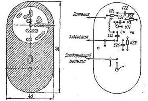
Rice.
4. Printed circuit board of the echo sounder: o - printed circuit board;
b - arrangement of elements The paired pulse generator contains a single-shot DA4, two differentiating chains C13R10 and C14R11, as well as a video pulse amplifier made on one of the transistors of the DA5 chip (pins 9, 10, 11). Diodes VD2 and VD3 are included in the differentiating chains to limit pulses of negative polarity. The positive pulses at the outputs of the chains will be shifted relative to each other for a time equal to the duration of the monostable pulse, since the chains are connected to its opposite-polar outputs (pins 5, 10). The video pulse amplifier is also a mixer of the output pulses of the differentiating chains. Diagram G4 shows one of the output pulses of the DA4 monostable, and diagram G5 shows paired pulses from the output of the video amplifier.
The shifted pulse generator contains a differentiating chain C10R9 and a video pulse amplifier made on the second transistor of the DA5 chip (pins 6, 7, 8). This amplifier is also the output amplifier of the receiving path. The output pulses of the differentiating chain are fed to the input of the video amplifier through the contacts of the switches SA1, SB1 and the capacitor SP.
The receiving path is formed by a microphone VM, a radio pulse amplifier VT1 - VT4, a detector VD5 and a video amplifier on a DA5 chip. The radio pulse amplifier consists of one broadband choke stage VT1 and three narrowband resonant ones. Interstage connections in the radio pulse amplifier are capacitive. The detector is made using a half-wave circuit. The output voltages of the stages of the radio pulse amplifier are presented in diagram G8 - PO, and the output voltages of the entire circuit are presented in diagram G6.
At the single input of the trigger DD1 (pins 7, two pulses (paired pulses) are supplied during each clock cycle. At the zero-setting input (pins 2, 4), the trigger can be controlled by one or two pulses. Depending on this, the trigger can operate in two modes, which is illustrated by two diagrams G7. If the trigger is controlled not only by an induced pulse, which is always present in the output signal of the receiving path, but also by an echo signal, then during a clock cycle the trigger is set to each of the states twice. The operation of the trigger will not change if you use one of the shifted pulses. In these cases, the output reading of the calibrated indicator will correspond to the real or simulated depth. In the absence of an echo signal and a simulating pulse, the trigger is set to each of the states only once during the cycle: by the induced signal and the second paired pulse, and the output reading of the indicator will be equal to the maximum measurable depth, i.e. 50 m.
Rice. 5. Throttle amplifier circuit board
The output voltage to the indicator is taken from pin 1, which is usually the inverse output of the trigger. Resistors R18, R7 and R8 are used to set the required current strengths of the PA1 indicator in the corresponding measurement ranges. The negative terminal of the indicator is supplied with bias voltage from the divider R21, R22. It is designed to compensate for the systematic error that occurs due to the return of the trigger to the zero state by the induced pulse, as well as due to the difference from zero in the output voltage of the trigger in the case when it is in the zero state. To prevent the indicator needle from shaking, capacitor C9 is used. The indicator also controls the power supply voltage of the echo sounder. The voltage of the power supply GB1 is supplied to the indicator through an additional resistor R20.
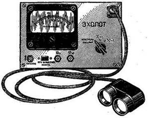
Rice. 6. Appearance of the echo sounder
The supply voltage of some of the device components is stabilized using a VD4 parametric stabilizer.
The device is mounted on a board made of fiberglass foil on one side with a thickness of 1.5 mm. Printed wiring and arrangement of elements on the board are shown in Fig. 4. The first stage of the radio pulse amplifier is mounted on a board made of double-sided foil fiberglass with a thickness of 2...3 mm (Fig. 5), on which the emitter and microphone are also installed.
The foil on the second side of this board is not etched for better shielding of the emitter-microphone unit. The dimensions of the board are given on the assumption that the driver and microphone are made using piezoelectric disks with a diameter of 30 mm. When using other drives, the board dimensions should be proportionally reduced or increased.
The following radio components are used in the design of the echo sounder. Fixed resistors - M LT, variable resistors R7 and R8 - SPO-1, tuning resistor R21 - SPZ-b. Polar electrolytic capacitors - K50-6 and K50-9 for a voltage of 10 V.
Capacitors C1, C2 - K76-P1 or K76-2; capacitors C5, C6, C25, C29 SZZ - PM-2 or FT-2; the rest are KM-5 or KM-6. Switch SA1 is a biscuit switch with 3 positions and 4 directions, SB1 is a push-button switch with locking, SA2 is a MTl microtoggle switch. Transformers and chokes are made on toroidal cores made of 1000NM or 1000NN ferrite. Transformer T2 is wound on a core K17.5 X 8, 2 × 5, and for the manufacture of other winding products, cores K10 X 6 X 4.5 or K12 X 8 X 3 are suitable. Transformer T1 has 80 turns in the primary winding with a tap from 60 turns , and in the secondary - 5 turns in each section. Transformer T2 in each section of the primary winding has 30 turns, and the secondary has 160 turns. The TZ transformer has 60 turns in the primary winding and 90 turns in the secondary winding. Chokes LI, L2, L3 are the same and have 100 turns each. All winding products are made with PEV-2 wire with a diameter of 0.16 mm. Connector XI is a four-pin connector from the 2PM or PC4 series. Two 3336L elements or 6 373 elements are used as a power source. Almost any microammeter with a total deviation current of 50 or 100 μA can serve as an indicator. Two uniform scales should be made on it in accordance with the measurement ranges and a power control mark should be applied. The device is made in a metal case measuring 240 X 160 X 70 mm (Fig. 6). The front panel contains the PA1 indicator, switching devices, resistors R7, R8 and connector XI. Resistor R20 and capacitor C9 are mounted on switch SA1.
Rice. 7. Design of the emitter-microphone block
The BQ emitter, the VM microphone and the first stage of the radio pulse amplifier are made in the form of a separate unit connected to the echo sounder with a cable. The design of this block (Fig. 7) provides electrical and acoustic isolation of the microphone from the emitter. The block is made as follows. To each side of two identical piezoelectric elements 1, taken from the same batch, three pieces of MGTF-0.1 or 0.14 wire, 60 mm long, are soldered with the necessary precautions. The soldering points should be at the edge of the piezoelectric element and located evenly around the circumference. Using “88” or “Moment” glue, a washer 2 made of microporous rubber is glued to each piezoelectric element. The diameter of the washers is equal to the diameter of the piezo elements, and the thickness is 5...8 mm. After the glue has dried, the leads soldered to the piezoelectric elements are collected into a braid on the side of the rubber washer and tied with thin cotton threads. The axis of the braid must coincide with the axis of the piezoelectric element. The solder in the soldering areas on the free side of the piezoelements, which will be the working side, must have the same height. You should check this with a probe and, if necessary, remove excess solder with a file or sandpaper. Piezoelements with washers are filled with epoxy resin in cylindrical cups bent from aluminum strips 1 mm thick. The inner diameter of the glasses should be 3...4 mm greater than the diameter of the piezoelements, and the height should be 4...5 mm greater than the height of the piezoelements together with the washers. Before pouring, the inner surfaces of the glasses should be lubricated with machine oil to prevent the glasses from sticking, and the outer surfaces of the piezoelements should be degreased. The pouring is carried out on a flat base, placing a sheet of organic glass on it. Glasses are placed on the glass, fixing their position with plasticine. Plasticine also prevents resin from leaking out. Prepared epoxy resin is poured into each of the glasses to a third of their height and piezoelectric elements with washers are immersed in it, orienting their position relative to the glasses. Then resin is added until the glasses are filled, from which the resin is emptied after hardening. Cylinders made in this way ensure complete sealing of the piezoelements and have almost identical resonant properties.
Protective glasses 3 are made from brass 1.6 mm thick, the height of which is 10 ... 12 mm greater than the height of the filled cylinders. The inner surface of these glasses is covered with vacuum rubber 4 with a thickness of 1.5 or 2 mm. The internal diameter of the rubberized cups should be 2...3 mm larger than the diameter of the filled cylinders. In the rubberized glasses, one hole with a diameter of 8 mm is made, through which air is displaced when the block is immersed in water. The holes are made at such a level that the piezoelements are completely in the water. Then washers 5, having holes in the centers and made of vacuum rubber 3...4 mm thick, are glued to the bottom side of the board 6. Their diameter should be equal to the internal diameter of the rubberized glasses. Filled cylinders are glued to the washers, passing the leads of the piezoelectric elements through the holes in the washers and the board. The gluing of washers and cylinders is carried out on a flat base using clamping weights, which ensures parallelism of the working surfaces of the emitter and microphone. After the glue has dried, rubberized protective cups are installed on board 6, soldering them around the perimeter. After this, the emitter and microphone leads are unsoldered, the elements of the VT1 amplifier are mounted (in Fig. 7 this amplifier is indicated by position 7) and the cable conductors 8 are soldered. Board 6 does not have holes for installing radio elements. Their installation is carried out on contact pads. Subsequent filling of this side of the board with epoxy resin will ensure the necessary fixation of conductors and radio elements. The leads soldered to the working side of the piezoelements should be connected to the body contact pad. The signal pins are soldered to the side to which washer 2 is glued. This measure provides better shielding of the microphone. The housing pad is connected to the foil on the back of the board through a hole. Cable 8 must have a length of at least 2...2.5 m for ease of handling the echo sounder when measuring depth in various conditions. Braids of shielded wires are soldered to the body contact pad. All cable conductors must be enclosed in a rubber tube. Before filling the board, you should check the functionality of the emitter and microphone with amplifier. This check is carried out during setup of the device.
To set up an echo sounder, in addition to an ampere-voltmeter, you will need an oscilloscope and a flat metal sheet of any thickness measuring 200 X 200 mm, which will serve as a reflector of acoustic signals. The device is configured and calibrated on both bands in the air, which is possible due to the use of a separate microphone to receive acoustic signals.
The setup begins by selecting the required resistance of resistor R20. In this case, switch SA1 must be set to the “Control, power” position. By selecting resistor R20, we ensure that the indicator reading on the “10 m” range scale corresponds to the voltage value of the power source GB1. In the future, the PA1 indicator with an additional resistor can be used as a voltmeter to determine constant voltages at various points in the circuit. To do this, unsolder the wire leading to resistor R20 from switch SA2, and use this wire as a probe. The VD4 stabilizer should provide an output voltage of 6.3 V ± 10%, and it should remain unchanged when the voltage of the GB1 source decreases to 8 V. It is advisable to select the zener diode and resistor R41 separately and then install it on the board.
The supply voltage for the microcircuits is supplied from the VD4 stabilizer (with the exception of the collector supply of two transistors of the DA3 assembly, on which the power amplifier is made). You should check the presence of these voltages at the corresponding pins of the microcircuits. At pins 6 and 10 of the DD1 trigger, the voltages should be 6V ± 10% and SV ± 10%, respectively. If this is not observed, then resistors R16 and R17 should be selected accordingly. They also monitor the presence of supply voltages for stages VT1 - VT4 of the radio pulse amplifier, which should be equal to 5, 6, 7 and 8 V, respectively.
Then set the range switch to the “10 m” position and begin setting up the circuit using an oscilloscope. The oscilloscope is used in external synchronization mode, and the synchronizing voltage is removed from the switch lamella SA1.1, connected to the inputs of microcircuits DA2, DA4 and the differentiating chain C10R9. By sequentially connecting the oscilloscope input to sockets G1 - G4, they control the operation of the DAl, DA2, DA4 microcircuits and the probe pulse generator.
Having verified the operation of these nodes, the final installation of the required durations of their output pulses is postponed until the generator of the probing pulses and the nodes of the receiving path are configured. For this setup, the emitter-microphone unit is installed half a meter from the metal sheet so that the working surfaces of the emitter and microphone are parallel to the plane of the sheet. The oscilloscope input is connected to the gate of transistor VT2. By selecting capacitor C6, we achieve a filling frequency of the probing pulse at which the echo signal has a maximum amplitude. The maximum echo signal will indicate that the filling frequency of the probing pulse coincides with the resonant frequency of the emitter and microphone. The amplitude-frequency response of the VT1 choke amplifier in the range of possible values of resonant frequencies is close to uniform and will not affect the correct setting of the generator when using piezoelements of any of the above sizes. It is advisable to check the correctness of the generator settings by the behavior of the amplitude of the probing pulse when its filling frequency changes in the vicinity of the found resonance. The amplitude of the probing pulse at the resonance frequency of the emitter will be minimal, since at the resonant frequency of the mechanical vibrations of the piezoelectric transducer, the modulus of its complex electrical conductivity takes on the maximum value. By selecting the capacitance of capacitors SZ and C4, it is ensured that the probing pulse contains 12...15 periods of high-frequency oscillations. If the trailing edge of the probing pulse is prolonged by more than 5...7 periods of high-frequency oscillations, the resistance of resistor R6 should be reduced.
By sequentially connecting the oscilloscope input to sockets G8 - G11, the stages of the radio pulse amplifier and the detector are configured. The radio pulse amplifier is the most critical part of the echo sounder, and special attention must be paid to its configuration. The gain must be such that on the oscilloscope screen it is possible to reliably distinguish an echo signal received in the air from distances up to 10 m, and trigger DD1 can be set to zero without failure in the echo signal received from a distance of 2.5...3 m. In this case, the amplifier should not be excited, but the amplified voltage of self-noise
microphone should not affect the operation of the trigger. When setting up the amplifier, you must strive to ensure that the duration of the induced pulse does not exceed 2t, since it is this that determines the minimum limit of the measured depths. The second paired pulse, returning the trigger to the single state, can be applied only after the induced pulse. Otherwise, under the influence of the latter, the trigger may return to the zero state again and there will be no pulse in its output voltage, the duration of which is proportional to the measured depth. Consequently, the echo sounder will not measure depths from which the echo signal arrives before the second paired pulse. The size of this “dead zone” is entirely determined by the duration of the induced pulse. It can be reduced by shunting the microphone output with a resistor, selecting its resistance experimentally (this resistor is not present in the circuit diagram). This must be done with the emitter-microphone unit immersed in water, since the mechanical vibrations of the microphone in air will differ from vibrations in water due to the difference in the acoustic impedances of these media. The block is placed on the bottom of the container with the working surfaces down and water is poured into it to the level of the centers of the holes in the protective cups, avoiding water getting on the installation of the VT1 amplifier that is not filled with resin.
By selecting the capacitance of capacitors SI, C12, the required duration of the output pulse of the one-shot DA4 is established, which determines the interval between paired pulses. The second paired pulse should lag relative to the decay of the induced pulse by 150...200 μs.
The amplitudes of the pulses arriving at the zero and one inputs of the trigger must be at least 5 V, which ensures the stability of its operation.
Subsequent adjustments are made again in air. The circuit for the passage of simulating pulses is checked on both ranges in the absence of an echo signal. These pulses are applied to the zero input of the trigger when the SB1 button is pressed.
The required half-cycle durations of multivibrator DA1 are selected as follows. The range switch is set to the “10 m” position, and the emitter-microphone unit is placed at a distance of 2.33 m from the metal sheet. Orientation of the radiation pattern is carried out by monitoring the output voltage of the radio pulse amplifier using an oscilloscope. The maximum amplitude of the echo signal will indicate the correct orientation of the block. By selecting the capacitance of capacitor C2, we ensure that the positive drop in the output voltage of the multivibrator coincides with the beginning of the echo signal. The duration of the second half-cycle is set by selecting the capacitance of capacitor C1, increasing the distance between the emitter-microphone unit and the sheet to 9.3 m, which corresponds to a depth of 40 m. In this case, the range switch should be in the “50 m” position. For each of the capacitors Cl, C2, there are three mounting positions on the printed circuit board, which makes it possible to select the required value by connecting the capacitors in parallel.
After setting up the transmitting and receiving paths, make sure that the trigger operates correctly in the presence of an echo signal from a distance of 0.5...1 m, without an echo signal and with simulating pulses that are supplied to the trigger input in the absence of an echo signal.
Setting up the echo sounder ends with adjusting the divider R21, R22, which is done as follows. The range switch is set to the “10 m” position, and the emitter-microphone unit is placed at a distance of 233 mm from the sheet, which corresponds to a depth of 1 m. By adjusting the resistor R21, set the indicator arrow to the 1 m mark. Then the distance is increased to 2.33 m and the resistor R7 set the arrow to the 10 m mark. Set the distance again to 233 mm and use resistor R21 to return the arrow to the 1 m mark. Through several rearrangements, ensure that the indicator readings correspond to the measured distance. By dividing the distance of 2.33 m into ten equal parts and designating the resulting marks with the numbers 0, 1, 2, 3..., we obtain the “air equivalent” of a depth scale from 0 to 10 m, with the help of which we check the accuracy of the echo sounder readings. The readings in the “50 m” range are checked only at distances from which the echo signal reflected from the sheet has sufficient amplitude to return the trigger to the zero state. Before checking the range, in the absence of an echo signal, use resistor R8 to set the indicator needle to 50 m and check its reading with the SB1 button pressed, which should be equal to 40 m.
After this, screen 9 is installed on the emitter-microphone block (see Fig. 7), soldered to board 6 at several points, and filled with resin. The screen is made of a brass sheet with a thickness of 0.5...0.8 mm. The bracket designed to secure the block in place should also be poured into the resin.
Transformers and chokes installed on the printed circuit board should be impregnated with varnish, and the board itself should be coated with it on both sides. Protection of radioelements from moisture, the use of highly stable capacitors in timing circuits and stabilization of the supply voltage of microcircuits ensure the specified metrological characteristics of the echo sounder. Careful design and configuration of the device ensures its high reliability when operating in various climatic conditions.
Before starting to work with the device, you should make sure that it is functioning correctly in all modes, which guarantees the reliability of the results of subsequent measurements. This check is carried out in the air, using any nearby flat objects as a reflective element: boards, a flat surface of the ground or water, the body of the echo sounder itself, etc. By installing the emitter-microphone unit at a distance of 0.5...1 m from the reflective surface, the readings are checked indicator on both ranges. This reading is 4.3 times the set distance. The block is then positioned so that there is no reflected signal. In this case, in the “10 m” range, the indicator arrow should go off scale, and when the SB1 button is pressed, it should be set at 10 m. In the “50 m” range, the reading of the PA1 indicator should be equal to the maximum value of the depth measured by the echo sounder, i.e. 50 m, and with the button pressed - 40 m.
To maintain the accuracy of the echo sounder at a given level during operation, it is advisable to periodically monitor its calibration by comparing the duration of half-cycle oscillations of the DA1 multivibrator with the time of arrival of the echo signal in the air from distances of 2.33 and 9.3 m.
Literature
BokitkoV., BokitkoD. Portable echo sounder. - Radio, 1981, No. 10, p. 23 - 25.
Kravchenko A. Transistor echo sounder. - Radio, 1973, No. 12, p. 15, 16.
OCR Pirate
Tweet Like
- Previous entry: ELECTRIC MOTOR-DISC
- Next entry: ELECTROACUSTIC COMPLEX “EDELWEISS”
- finally block (0)
- Class functions (0)
- ref and out parameters (0)
- Assembly language examples of commands (0)
- Features of microcontroller development (0)
- FPGA based controllers (1)
- TECHNOLOGICAL TIPS FOR MANUFACTURING AND ORIENTING A TV ANTENNA (0)
Related posts:
Main characteristics of the sensor

The efficiency of a device is primarily determined by its power. For portable sonars it rarely exceeds 300 W. Models with this potential are optimally suited for regular fishing from the shore with a casting range of about 30-40 m. Power affects the detection depth, which can reach from several tens to hundreds of meters - most models operate in the range of 40-500 m. The frequency will also affect the emission range. The lower it is, the higher the range of action. For example, 50 kHz will provide the same 500 m. But it is important to consider that the function of the wireless echo sounder sensor for a smartphone will also be affected by the characteristics of the water. Thus, in conditions of increased mineralization, the monitoring depth can be halved. However, you should not focus solely on power versus frequency. The scanning angle is also important, which on average varies from 15° to 45°. This is the amount of coverage of the underwater space - accordingly, from a narrow field to a wide one.