Alternative terms
One of the sections in the electrical network is a wire connection, which is connected at one end to the substation buses.
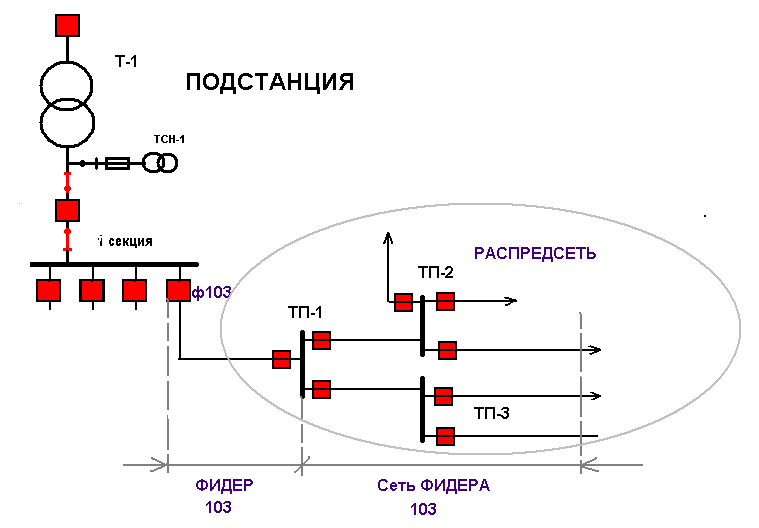
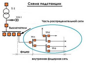
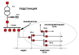
Essentially, it supplies electricity to the part of the electrical network that is connected to the other end of that connection. In English this action is called feed. Accordingly, the direct executor thereof will be called feeder. The feeder is connected to the substation buses via switch F (see image below). On the other hand, a switch is also required, which is part of the distribution network. For the entire section of the network that starts from switch F and extends to the right in the image shown below, the definition of “feeder” in the broadest sense of the term can be applied. However, the feeder itself is the electrical connector connected to the switch F and the switch of the TP-1 substation.
What is a feeder
In this narrower sense, the term “feeder” in the electric power industry is most often used in cable networks. For example, there may be messages like this:
- The feeder is damaged. Consequently, the fault appeared precisely in the conductor itself (feeder) between the switches F and at the TP-1 substation. This section is called the head section.
- When it is said that the feeder was disconnected, or a fault appeared in the feeder network in such and such a cable. That is, this damage occurred outside the head area.
And in a broad sense -
- when a feeder trip is mentioned, meaning that breaker F has tripped and the power supply to the feeder network consisting of the substations supplied by that feeder has been interrupted.
- When talking about unloading the feeder from the substation, it means unloading the entire feeder network from the substation.
As mentioned above, the term “feeder” has been in use for a long time. But since this word is of English origin, it is not always and everywhere widely used. Although there are many different documentations with the designations "feeder" or "feeder cell", the word "line" is also widely used instead of the English terminology.
Therefore, we can call the corresponding section of the electrical circuit located between the substation buses at the input and output of the power supply system, both the feeder and the outgoing line. And in our everyday life, a feeder, in fact, is every electrical cord connected to a 220 V power outlet.
Content
- 1 Feeder rod classes 1.1 Ultra Light feeder (Picker)
- 1.2 Light feeder
- 1.3 Medium feeder
- 1.4 Heavy Feeder
- 1.5 Extra Heavy Feeder
- 1.6 Swingtip
- 2.1 Fast formation
What is an electric feeder?
Any electrical network is designed to transmit electricity from source to consumer. But at the same time it contains a large number of different components.
To highlight certain areas in the electrical network for the purpose of systematization, special names are used.
Next, we will tell readers about what a feeder is in electrics and how to distinguish a feeder cable, as well as some other nuances that distinguish feeders from other electrician terms.
The owner of the house has to master a huge amount of information that has nothing to do with his professional activities. It’s just different communication with representatives of various organizations that supply us. Very few people can explain in simple terms what happened or what they need.
The content of the article
Definition
No one can say unequivocally what an electric feeder is. An overly broad definition that applies to various parts of the power supply circuit, from some power transmission system devices to a section of cable. Let's figure it out so we have an idea of what we're talking about. Let’s say right away that we will be talking about a feeder in power supply or radio transmission.
The word “feeder” comes from the English feeder, which in one version is translated as “power line”. But in different situations we understand this name as different parts of the circuit. There are no precise definitions in textbooks or standards. A 1950 textbook has the following definition: “A feeder is a power transmission line from a switchboard (panel) to another switchboard or large unit. »
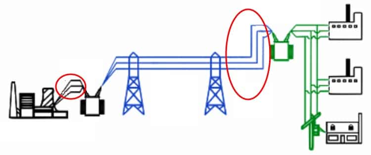
The power line from the power plant has at least two feeders
That is, in essence, an electrical feeder is a certain section of power supply lines. But does it only include power lines and the devices through which they are connected? But in different ways. Depends on the situation. This concept is mainly used by specialists. But in various situations you have to communicate with them, so you need to know what they are talking about. Otherwise it is impossible to understand them.
The easiest way to understand the terminology is to give specific examples. First, let's look at the radio feeder. There are practically no discrepancies here, since the schemes are typical. The figure below shows a diagram of the organization of radio communications. There is a signal receiver and transmitter. There are receiving and transmitting antennas. Between the receiver/transmitter and the antenna there is a cable connection (coaxial cable) through which the signal is transmitted. So, this section of the cable is called a radio feeder.
Radio channel organization diagram
To further clarify what a feeder is in radio communications, let’s consider a regular antenna, one of those that we use to receive radio or television signals. This is the receiving side of the circuit, and the receiver is the radio or television.
One of the options for household antennas (the feeder is a piece of cable)
As you can see in the picture, the antenna feeder is a piece of cable that goes to the receiver. Antenna designs may be different, but they always have a feeder.
More examples of antenna feeders
To summarize, for antennas, the feeder is the section of cable through which the signal is transmitted from the antenna to the receiver, or from the transmitter to the antenna. This one is simple.
Electric feeder
Understanding what a feeder is in a power supply network is more difficult. This is because the concept is not defined and is used in different ways. A feeder can be called a section of cable between the switch and the distribution network, an input switch, a transformer and devices connected to it, a cable from the transformer to the switchboard, etc. Let's look at the example of substations.
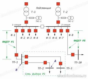
One example of a substation
This figure shows a diagram of one of the substations with four sections. Each site has its own electrical feeder with appropriate devices. In this case, the feeder is called:
- The cable section from switch F4 to the switch at TP1. This is the so-called “narrow concept”. It is used when a section of the cable is damaged.
- The entire section of the network - from switch F4 to the devices to which lines that go beyond the substation are connected. In the figure, this is the zone that falls into the oval. This is a "broad" concept. It is used when some equipment in this area (but not the head cable) is damaged.
In any case, the substation feeder is the diocese of electricians and there is nothing you can do. Just wait until they determine the area of damage and fix it.
Few of the power grid workers speak “human language.” Their messages must be translated from a special dialect to a “general” one. And not each of them can clearly tell what exactly he told you, without using complex or incomprehensible words. We will try to explain a few common expressions.
READ MORE: Connecting an electric boiler to a gas boiler; work technology
There can be many different devices in a feeder distribution network. These are high-voltage switches (the correct name is “switching devices”), arresters, current and voltage measuring transformers, insulators, buses. Cable or overhead lines are connected to the buses. And all this can be called the word “feeder” for the general definition of the damaged area.
Then, as the damage is determined, the area is specified. But first they say “the fourth feeder has switched off” or “the fourth feeder is damaged.” When the cause of the shutdown has been found out, and it is a cable or one device on the transformer substation, they can clarify that the damage is “in the feeder network” or “feeder network” and further clarify what exactly is faulty - the feeder cable, the feeder circuit breaker or switch, another device. But ordinary “mortals” are not given such information.
Such transformer substations are common. Usually they are designated TP-1, TP-2, etc. on the diagrams. If we consider them, the electrical feeder is partially located inside (different devices), part is an overhead line to the next switchboard
When they say “Electrical feeder has gone out,” it usually means that a certain area is without power. In some schemes, it is possible to switch the load (consumers) to other feeders (sections) so that consumers are not left without power supply while the damage is repaired. But such schemes are usually developed for enterprises, organizations and other significant objects. Private houses are not included in this list.
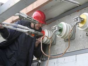
If you are a home owner and you have been told that your feeder is damaged, most likely you have been told that there is a problem with the cable that runs from the panel on the pole to the input switch. That is, you need to change the cable or look at the connection points. Maybe the terminals have oxidized, maybe the contact on the switch.
Personnel who work with an electrical network with a voltage of less than 1000 Volts do not always understand what is happening “at the other end of the line.” However, the electrician must have an understanding of the power supply scheme for the area or village. In electrical engineering you can often come across the expression “electric feeder”.
In fact, there are several variants of the concept of this word. So what is it and what does an electrical feeder look like? This can be a network that powers transformer substations, connecting them to a specific switch, which is used in mains from 6 to 10 kV. If the cable that connects the transformer to the switch is damaged, it means that the electrical feeder is damaged.
There are many opinions regarding which part of the lines should be called feeders. Or will it be the entire feeder line, or will it just be the main section that goes to the first substation? The general meaning implies the entire network going from the equipment to the substation. If we look at it more narrowly, this is part of the cable that goes to the first transformer.
If you look at the designations by industry, then in the electric power industry, an electric feeder is an overhead line that connects two substations to each other or connects a substation to a distribution mechanism. At the same time, do not forget about the fact that this device is connected to the power that is supplied to electrical equipment. Therefore, it is also commonly called the main line, which connects the substation directly to the distribution node.
In the case when an electrical network is being designed, this definition refers to the cable through which power is supplied to the consumer from the distribution device. Or power can be supplied from one distribution node to another. The same lines that are diverted beyond the distribution device are called “branch lines”.
Electric feeders can be of two types: cable and overhead. But this does not change the fact that they serve as a connection between the busbars that are present in the distribution nodes of substations (whether converter or transformer) and the electrical network itself (consumer or distribution).
For example, in power supply, such a definition was given to a section of a traction network that connects a traction substation with a cantata power network thanks to voltage buses. The electrical feeder is equipped with a special protective device that protects against overloads and short circuits thanks to the presence of automatic switches. These switches disconnect the contact network if the protection ratings are exceeded. A high-voltage disconnector can also do this.
How the feeder line is displayed on the diagram
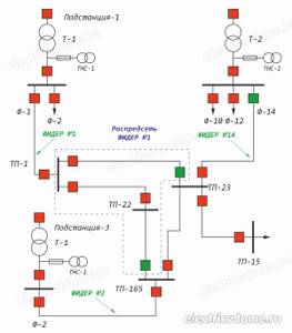
As an example, we can consider part of the circuit of a high-voltage substation, consisting of a 154/6 kV transformer T1 and step-down transformer substations TP1-TP3, consisting of bus sections and 6/0.4 kV transformers not indicated on the diagram. This will help you understand what a feeder is in electrical engineering.
In this diagram, the feeder is all the circuits connected to cell F1. These are sections of the power supply diagram designated by the letters “A” and “B”.
It is also allowed to consider only the circuits feeding substations TP1-TP3 as feeders. In the diagram, this section is designated “B” and is the F1 feeder network.
If it is necessary to turn off a given section, then the corresponding switch in the cell is turned off. For example, to turn off feeder “B” it is necessary to turn off the switch in cell F1. If they say that the feeder is damaged, then this means an accident on the entire section “B”.
Using this term allows you to indicate a section of the circuit, but does not indicate the location of the damage. This could be one of the cable lines, a disconnector or switch located on the same line.
In order to avoid confusion, the concept of “feeder” is used only in conversations, and in documents alphanumeric markings of electrical circuit elements are used.
Feeder for electricians
Substation workers, like representatives of many other professions, have their own “language” that is poorly understood by mere mortals. In order for these expressions to be understandable to ordinary people, they need to be deciphered:
- Feeder. Its circuit can contain a variety of devices - oil switches, disconnectors, cables, overhead lines, control and automation systems.
- The third feeder switched off or an emergency shutdown of F-3 occurred. This expression is used when there is an emergency network shutdown due to the activation of protection systems.
- The third feeder is damaged. The phrase is used when protection is triggered due to damage to the line or breakers.
- Fault in the feeder network or in the feeder network. The expression is applied after specifying the location of the accident and is supplemented by an indication of the faulty element.
- The feeder has switched off. This means that the step-down transformer and the consumers connected to it were left without power. Some industries have the ability to switch to other power supply schemes, but for residential buildings this option is usually not available.
- Your feeder is damaged. This is what electricians tell owners of private houses or residents of apartment buildings. Most often, this means that the network is damaged in the area from the power line pole to the input circuit breaker or switch. This could be a broken cable, oxidized terminals or connection point on a pole or in a water shield.
The concept of “feeder” and other related definitions are convenient for indicating a specific part of the network. The disadvantage of this term is that it indicates several elements of the circuit at once, united by a common function.
This may lead to disagreements in the understanding of the causes and location of the accident by operational and repair personnel. Such misunderstanding is dangerous for workers involved in troubleshooting, therefore, when solving practical problems, it is more advisable to use official terminology, in which the term “feeder” is absent.
We advise you to study - The luminary emerges from the shadows
Similar materials on the site:
- How to plan an electrical wiring diagram
- Why is PUNP wire prohibited for use?
- Purpose of Phase and Zero
Electric feeder: what is it, device, purpose
The content of the article
Definition
In power engineering terminology, the word “feeder” appeared a long time ago. Soon after electricity supply began in England and the USA. Nevertheless, it is widely used because it is convenient for its brevity and semantic capacity. A powerful flow of electrical energy is directed through the feeder from the substation towards consumers.
Distribution networks typically operate at voltages between 6 and 10 kV. They regularly perform calculations of electricity losses every month. The accuracy of these calculations is essential for the formation of electricity tariffs. As it turned out, the loading of 10 kV feeders affects the results of calculations of electricity losses, as well as the analysis of technical losses. These conclusions were made on the basis of a study conducted in the Krasnoyarsk Territory in the power distribution networks of the Uzhursky district.
The studies were carried out using the REG10PVT computer complex. Losses in 35 feeders operating at a voltage of 10 kV and related to seven substations of the Uzhur Distribution Zone were studied. Feeder input data was used:
- installed equipment, its power and other characteristics;
- brand of wire used, its length;
- configuration of electrical circuit diagrams.
Based on the initial data, the steady-state modes of these 35 feeders were calculated, taking into account time and average ambient temperature. This made it possible to determine electricity losses in individual elements of the circuit of each feeder -
- in wires and cables;
- in transformers;
- identify losses in the low-voltage part of the network with a voltage of 0.4 kV;
- determine the total technical losses and how they relate to the amount of electricity supplied by the distribution network.
What is a feeder in electrical engineering?
The owner of the house has to master a huge amount of information that has nothing to do with his professional activities. It’s just different communication with representatives of various organizations that supply us.
Very few people can explain in simple terms what happened or what they need. So you have to be aware of most of the terms they use. For example, when connecting to the mains or when there is no light, we often talk about “electric feeder”.
Moreover, electricians themselves cannot always explain what it is.
Definition
The word “feeder” comes from the English feeder, which in one version is translated as “power line”. But in different situations we understand this name as different parts of the circuit.
There are no precise definitions in textbooks or standards.
In electrical engineering, a feeder is a circuit or transmission line, together with auxiliary elements, through which electricity flows from the source to the consumer. Moreover, it includes many components. To make it easier to navigate the electrical network, its individual sections are identified and special names are used.
READ MORE: Moldings in the interior, wall and ceiling methods of use 52 photos
This word has many meanings, not all of which relate to the electric power industry. Not every electrician will understand what is meant by the term “feeder”. This probably refers to the network that feeds the substation transformers and then connects them to a specific circuit breaker.
This mainly concerns electrical lines with voltages from 6 to 10 kV. In practice, a situation occurs when a common circuit breaker is turned off on a transformer device. In this case, they say that the feeder is disconnected. That is, it turns out that in this case the feeder is the line that supplies a specific element of the substation. It includes:
- high-voltage switching devices;
- discharge devices;
- instrument transformers;
- insulators;
- power cable and overhead power transmission lines;
- protection devices, etc.
The distribution equipment includes several feeders, which form the following devices: stationary, open, closed, complete for indoor or outdoor installation.
And also in the electric power industry, these include power transmission lines running from substation to substation or from substation to switchgear. A feeder is a line that connects an electrical substation to a distribution center.
Device Description
When designing and constructing an electrical main, feeders include cables that connect distribution equipment to consumers or other nodes. Lines that continue from a distribution facility are called branches.
Electrical lines can be either open or laid in trenches. In both cases, they perform the same task, namely, connect busbars in switchgear to consumer electrical objects.
For example, in traction power supply, the section of the network connecting the voltage buses with the contact network also refers to feeders. For their safe operation, the equipment is protected by circuit breakers and high-voltage disconnectors.
All structural elements that belong to these areas are called feeder equipment. Thus, a feeder is practically a power transmission line or a separate section of it that supplies electricity to substations or other distribution nodes.
If you use high voltage when transmitting electricity, this makes it possible to avoid large losses on high-voltage power lines and you can install cables of a smaller cross-section. This especially plays a big role when transmitting electricity over long distances, since in this case the current strength decreases, which affects losses.
Standard trunk lines transmit electricity with voltages starting from 110 kV. Distribution networks use a voltage of 10 kV, which is obtained at transformer substations where the main feeder, its cells and protective equipment are located.
The outlet line connects the secondary winding of the step-down transformer to the distribution equipment, from where the supply feeder lines originate. Usually, when further transmitting electricity to consumers, the term “feeder” is not used.
The parameters of the circuits directly depend on the operating voltage. Thus, in high-voltage traction transformer devices, switches contain both forms of protection. This equipment has a fairly high response speed. At the same time, it is controlled by circuits that provide the functions of current pulse and standard protection.
These types are the main protection against short circuits, and to increase their reliability, backup equipment is used. Feeders in a traction network are their most complex types. Since their location is directly connected to the contact wires, electric locomotives and electric trains constantly load the circuit while moving along the rails.
At the same time, the network load is directly related to the mass of the rolling stock and the terrain. In addition, the circuit begins to work hard when several electrical sections are turned off for repairs or maintenance. The efficiency of feeder protection is important for the safe movement of electric trains.
To do this, vacuum or oil circuit breakers are installed in the system, which are included in two-stage protection based on teleblocking and accelerated current shutdown. Structurally, the entire system is designed as a separate mechanism.
Recently, more and more often, instead of the term “feeder,” power engineers use the phrase “outlet line.” This fact has not yet been documented, so both meanings can be used.
Any electrical network is designed to transmit electricity from source to consumer. But at the same time it contains a large number of different components. To highlight certain areas in the electrical network for the purpose of systematization, special names are used. Next, we will tell readers about what a feeder is in electrics and how to distinguish a feeder cable, as well as some other nuances that distinguish feeders from other electrician terms.
Home » Dictionary of construction terms » F
Electricians working with low-voltage networks (low-voltage networks include civil and industrial networks with voltages up to a thousand volts, and not what you think) do not always have a clear idea of what is happening “on the other side of the transformer.”
This approach is partly justified, since the design of high-voltage transmission and distribution networks does not directly affect the circuitry and installation methods of household electrical wiring.
However, understanding the power supply scheme of a microdistrict, town or large enterprise will help create a complete picture of the state of energy in the region.
Fish spawning is a special period in the life of aquatic inhabitants. Spawning is determined by the presence in the reservoir of those favorable conditions to which this type of fish is adapted.
Spawning fish - salmon
Most of all, fish spawning depends on water temperature. Each type of fish has its own temperature limits that favorably influence spawning. If the water temperature goes beyond these limits, fish spawning may not occur at all or it may only occur partially.
Both the eggs and the young fish that hatch from them are very sensitive to heat and cold. A sudden change in temperature can kill fish eggs. From this we can conclude that most fish spawn during their spawning season, when the water temperature is most conducive to their reproduction.
Spawning time
Most of our freshwater fish spawn from spring to early summer. Pike spawning begins in early spring, usually mid to late April. From mid to late May, perch and ide spawn. From the end of May to the beginning of July - spawning of bream, roach, pike perch.
At the end of spring and beginning of summer, carp, silver bream, crucian carp, tench and other fish spawn. Trout and other salmon spawn in late autumn and early winter. And in the coldest time in January, burbot, the most cold-loving fish, spawns under the ice.
Spawning sites
Each type of fish gathers to spawn in special places, spawning grounds.
Spawning of pike, carp, bream, pike perch, silver bream, rudd, ide and other fish occurs mainly in river floodplains and grassy shallows. Spawning of sabrefish, asp, and chub occurs in fast currents. Spawning of ruffe, gudgeon, burbot - on a sandy or rocky bottom.
Most fish lay eggs during spawning. Females release eggs into the water, to the bottom or onto plants, and at this time male fish water them with milt - seminal fluid. As a result, the fish eggs are fertilized.
READ MORE: Repair of Electrolux dishwashers, typical breakdowns and restoration
Fertility, i.e. The number of eggs that a female fish lays during spawning varies from species to species. For example, a female carp lays up to 3 million eggs during spawning. A female catfish spawns up to 500 eggs. What is the reason that some fish lay several million eggs, while others lay only a few hundred?
note
In most fish, fertilization of eggs is external. Therefore, both the eggs and the larva of the fish, which hatch two weeks after spawning, face many dangers in nature. A significant amount of eggs is not fertilized due to the lack of necessary conditions for fish spawning. Some of the eggs are carried away by the current and eaten by fish, amphibians, birds, insects and other animals.
Experiments have established that of the eggs laid by female carp, 97% of the fry do not reach the age of three, and 93% of the fish die within the first 7 - 10 days after spawning. This is explained by the fact that the early period of life in fish, like in other animals, is the most vulnerable. It is estimated that in some fish only one individual out of a thousand fry becomes an adult.
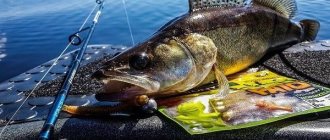
Feeder fishing and feeders for it
The main function of feeders for feeder fishing is to deliver the finished bait to the place where the fishing will take place, and also to make sure that the bait there “opens up” to its full potential.
If you make the wrong selection for certain conditions, then the desired result cannot be achieved. Simply put, the fish will not stand in one place, and we will not be able to attract it.
The following types of feeders are distinguished according to the method of their use:
- For feeding the starter;
- For long-distance casting;
- Additional feeding troughs for standing waters;
- Additional feeding troughs for ponds with currents.
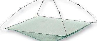
Feeders for feeding starters
This model differs in its size and cell size. These kormacs have large cells. The food is washed out of them quickly. They are used in cases where it is impossible to throw a molded ball of bait far by hand.
Before you start fishing, you need to cast the starting feeder for feeder fishing about ten times. When the feeder falls to the bottom, you need to make a sharp sweep to ensure its cleaning. This is done several times.
Additional feeding troughs for standing waters
This is the same option as described above, only in a smaller form. What shape it will be is also not particularly important. The main thing here is that the cells have a size that will allow the bait to work without obstacles. It should be gradually washed out of the cell.
Feeders for supplementary feeding serve as a holding factor for fish. During fishing, such a system stimulates the appetite of nearby fish, as the food is washed out in small portions.
Supplemental feeding troughs for ponds with currents
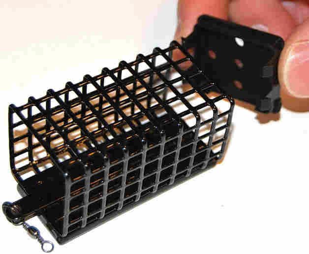
Here the shape of the feeder plays an important role. For current conditions, cormak are used, the bottom of which is weighted, and the cells are small. This is necessary to ensure that the equipment is held in one place. In places where the current is strong, closed feeders are used.
For long casting
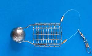
Most often, feeders resemble a badminton shuttlecock. The cell may close completely or partially. When casting, their behavior is also similar to that of a shuttlecock. The front of the feeder has a weight that stabilizes its flight.
If we compare the flight range of conventional cormacs and current cormacs, the latter fly 25-30% further.
What the research showed
As a result, a standard for reporting electricity losses was obtained. Both electrical power and percentage display were used to evaluate it. Data on losses in all feeders were summarized and formed the basis for constructing the graphs presented below. These graphs show:
- the predominance of idling power losses of transformers over load losses;
- reduction in the share of technical losses with an increase in the throughput characteristics of the feeder against the background of a slight change in no-load losses of transformers;
- The loss standard increases if at no-load in transformers, due to their design features, there are significant no-load losses, leading to an increase in total technical losses.
Further on the graphs, the network load is shown on the abscissa axis, and the main losses are shown on the ordinate axis.
Table 1
Studying the flow of electricity through feeders allows us to construct the graphs shown above and draw the following conclusions:
- With an increase in the flow of electricity through the feeder (its head section), load losses increase, as does the total network load. At the same time, the standard for electricity losses mostly consists of the total technical losses.
- Changes in the standard mainly depend on losses in wires and cables, and not on load losses in transformers.
Electric feeder in power supply: what is it?
A striking example is the feeder; this term can be found in the energy sector, radio engineering, as well as in the description of fishing gear and paintball equipment.
HomeMiscellaneousFeeder cable is
Personnel who work with an electrical network with a voltage of less than 1000 Volts do not always understand what is happening “at the other end of the line.” However, the electrician must have an understanding of the power supply scheme for the area or village.
In electrical engineering you can often come across the expression “electric feeder”. If we take the translation from England, it means supply or food.
There are many opinions regarding which part of the lines should be called feeders.
Or will it be the entire feeder line, or will it just be the main section that goes to the first substation? The general meaning implies the entire network going from the equipment to the substation.
Important
If we look at it more narrowly, this is part of the cable that goes to the first transformer. This term is considered more appropriate for cable networks. In an overhead power line there is no main section as such, since the cables run radially and are designated by simple numbers.
If you look at the designations by industry, then in the electric power industry, an electric feeder is an overhead line that connects two substations to each other or connects a substation to a distribution mechanism.
At the same time, do not forget about the fact that this device is connected to the power that is supplied to electrical equipment.
Therefore, it is also commonly called the main line, which connects the substation directly to the distribution node.
For example, in power supply, such a definition was given to a section of a traction network that connects a traction substation with a cantata power network thanks to voltage buses.
The electrical feeder is equipped with a special protective device that protects against overloads and short circuits thanks to the presence of automatic switches.
Advice
These switches disconnect the contact network if the protection ratings are exceeded. A high-voltage disconnector can also do this.
Equipment that is directly related to this device is called feeder equipment. For example, this could be feeder automation or a disconnector and feeder protection.
An electric feeder in electricity can also be called a distillation or stationary feeder. This is only true if it is used in traction electrical networks. Yes, and this will depend on those consumers who receive power from the network through a specific feeder.
In such cases, each line receives its own personal number.
It should be noted that such a concept can be easily replaced with the simple word “power line”, since the device is a kind of power line. And, despite the fact that such a line is considered the main line, it is also defined as a section of the electrical network that connects a certain number of remote devices to the main power line.
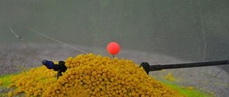
Lure
One of the main factors in catching fish is its attraction and retention at the fishing site. For these purposes, when fishing with a feeder (and during any other fishing for peaceful fish), bait is used. The bait is hammered into a special cage-shaped feeder. When choosing bait for fishing, you need to take into account many factors, and one of them is the stickiness of the bait. When fishing in still water, you can use loose aromatic bait, but if you use it on a river, the current will quickly carry it away, and nothing will be left of the bait stain. To do this, on rivers they use more sticky baits, weighing them down with earth or clay.
In addition to the plant components, an animal component is added to the bait: small “feed” bloodworms or small maggots. Fish love these insects, and their presence in bait will attract fish not only by smell, but also by movement.